
Buzzer driving circuit

A driving circuit and buzzer technology, applied in instruments, sounding devices, etc., can solve the problems of frequency stability and consistent driving current of easy-to-burn chips, and achieve gate voltage stability, oscillation frequency stability improvement, and driving current stability Effect

Active Publication Date: 2019-01-25
无锡十顶电子科技有限公司
View PDF10 Cites 0 Cited by
  • Summary
  • Abstract
  • Description
  • Claims
  • Application Information

AI Technical Summary

Problems solved by technology

[0003] The present invention provides a buzzer drive circuit to solve the problems existing in the prior art that the chip is easily burned when the power line and the ground line are reversed, as well as the frequency stability and consistency, and the stability of the driving current, while saving costs

Method used


Image

  • Buzzer driving circuit
  • Buzzer driving circuit
  • Buzzer driving circuit

Examples


Embodiment Construction

[0016] In order to make the purpose, technical solution and advantages of the present invention clearer, the present invention will be further described in detail below in conjunction with the accompanying drawings and specific embodiments.

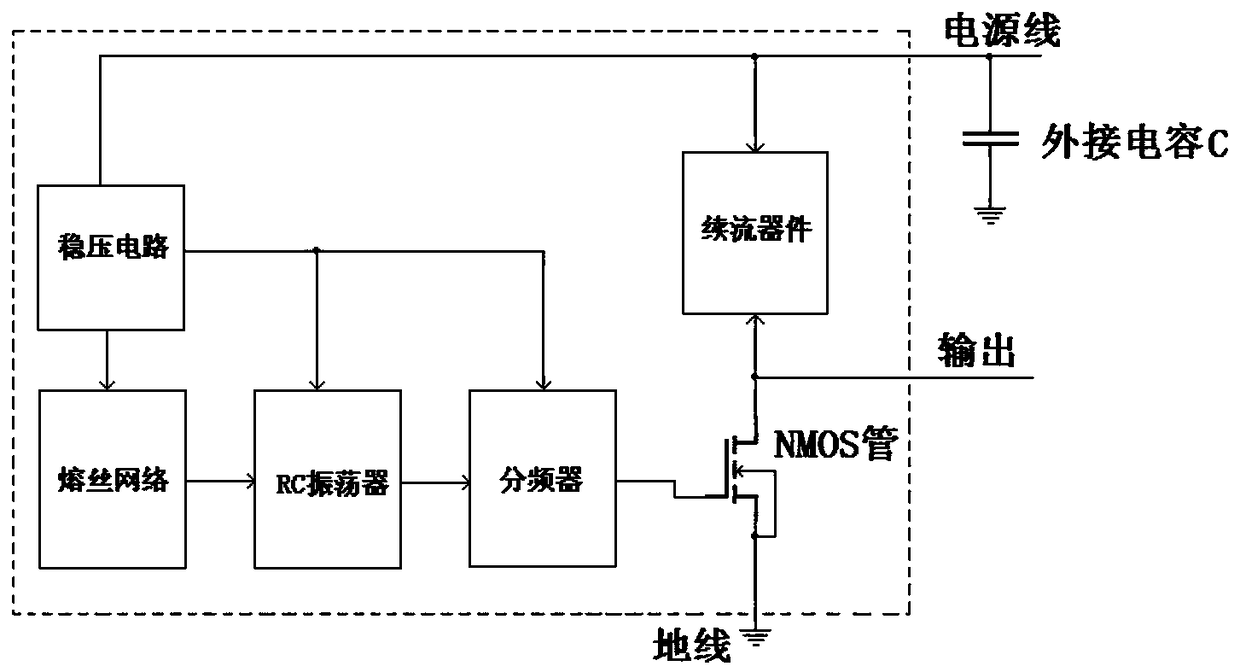
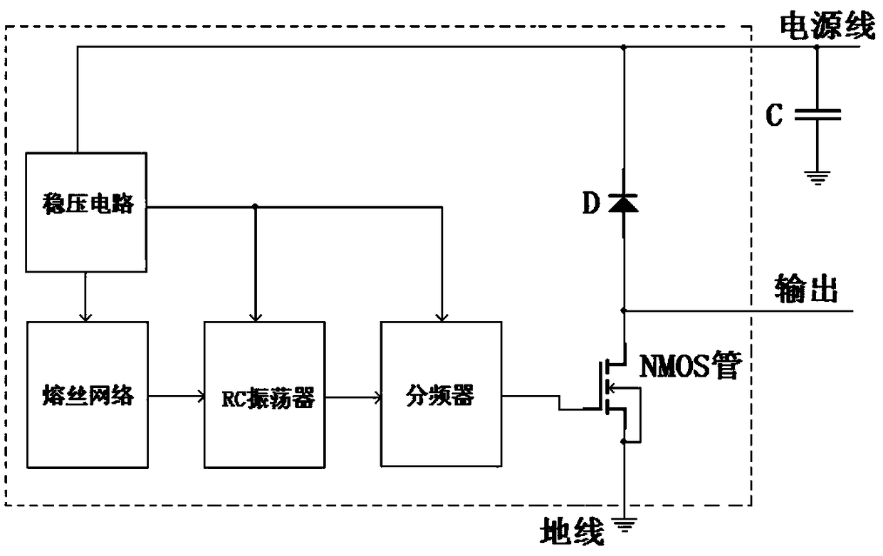
[0017] Such as figure 1 As shown, a buzzer driving circuit provided by the present invention includes a voltage stabilizing circuit, a fuse network, an RC oscillator, a frequency divider, a driving NMOS tube, a freewheeling device, and an external capacitor. The fuse network, the Both the RC oscillator and the frequency divider are connected to the power supply through the voltage stabilizing circuit, the output end of the fuse network is connected to the RC oscillator, and the output end of the RC oscillator is connected to the On the frequency divider, the output terminal of the frequency divider is connected to the gate of the driving NMOS transistor, the source of the driving NMOS transistor is grounded and the drain is connected to ...


PUM


Abstract

The invention provides a buzzer driving circuit, comprising a voltage stabilizing circuit, a fuse network, an RC oscillator, a frequency divider, a driving NMOS transistor, a freewheeling device and an external capacitor. In which the fuse network, RC oscillator, the supply terminal of the frequency divider are connected to the power supply through a voltage regulating circuit. The output of the fuse network is connected to the RC oscillator, the output of the RC oscillator is connected to the divider. The output terminal of the frequency divider is connected to the grid of the driving NMOS transistor, the source electrode of the driving NMOS transistor is grounded and the drain electrode is connected to the power supply through a freewheeling device, one end of the external capacitor is grounded and the other end is connected to the power supply, and the output terminal of the driving circuit is connected to the drain electrode of the driving NMOS transistor. The invention greatly improves the oscillation frequency stability of the RC oscillator, relatively stabilizes the driving current for driving the NMOS transistor, and avoids the burnout of most logic circuits of the circuitdue to excessive fluctuation of the power supply, which is favorable for preventing the chip from burnout when the power supply line is connected with the ground line.

Description

technical field [0001] The invention relates to the technical field of buzzer driving, in particular to a buzzer driving circuit. Background technique [0002] The traditional buzzer oscillation source generally uses a triode multivibrator circuit. The principle of this circuit is to alternately conduct the triode through the charge and discharge of the resistance and the capacitor. This traditional oscillation circuit has the following disadvantages: the frequency fluctuates with the power supply The change is large, because the devices used in the circuit are discrete devices, so the cost is high. And the kind of buzzer drive circuit made of integrated circuits, such as Figure 6 As shown, there are the following disadvantages: (1) The output frequency of this circuit changes significantly with the fluctuation of the power supply; (2) The eight-stage frequency divider is used in the circuit, which limits the design parameters of the previous RC oscillator, especially Comb...

Claims


Application Information

Patent Timeline
Patent Type & Authority Applications(China)
IPC IPC(8): G10K9/122
CPCG10K9/122
Inventor 张怀东
Owner 无锡十顶电子科技有限公司
Learn More