
Vehicle-mounted rotor wing unmanned aerial vehicle recovery guide system and method based on millimeter wave radar

A millimeter-wave radar and unmanned rotor technology, which is applied in radio wave measurement system, radio wave reflection/re-radiation, instruments, etc., can solve the problem of inability to realize all-weather recovery of rotor UAV, inability to realize vehicle dynamic recovery, and inability to adapt Various operational environments and other issues, to meet real-time requirements, improve recovery accuracy, and improve security

Pending Publication Date: 2019-01-25
JILIN UNIV
View PDF0 Cites 3 Cited by
  • Summary
  • Abstract
  • Description
  • Claims
  • Application Information

AI Technical Summary

Problems solved by technology

[0004] The technical problem to be solved by the present invention is to provide a millimeter-based The wave radar vehicle-mounted rotor UAV recovery guidance system and method can effectively improve the universality of the combat environment of the rotor UAV, and realize the autonomous landing and all-weather dynamic recovery of the rotor UAV

Method used


Image

  • Vehicle-mounted rotor wing unmanned aerial vehicle recovery guide system and method based on millimeter wave radar
  • Vehicle-mounted rotor wing unmanned aerial vehicle recovery guide system and method based on millimeter wave radar
  • Vehicle-mounted rotor wing unmanned aerial vehicle recovery guide system and method based on millimeter wave radar

Examples


Embodiment Construction

[0039] In order to show the present invention more clearly, the present invention will be further described below in conjunction with preferred embodiments and accompanying drawings. Those skilled in the art should understand that the content specifically described below is illustrative rather than restrictive, and should not limit the protection scope of the present invention. In order to avoid obscuring the essence of the present invention, well-known methods, procedures, procedures, components and circuits have not been described in detail.

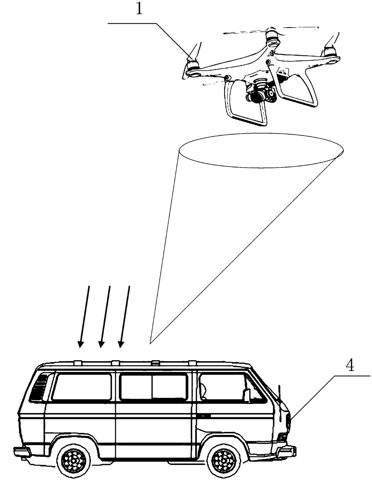
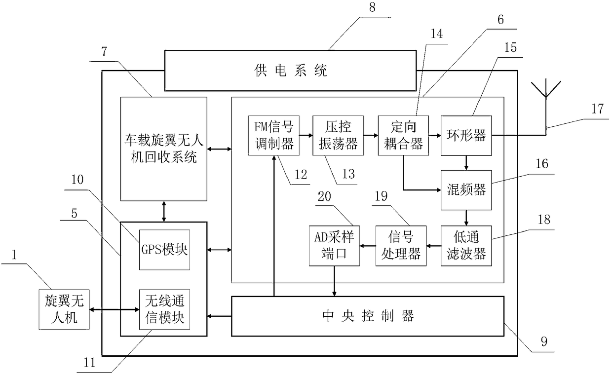
[0040] refer to figure 1 and figure 2 , the vehicle-mounted rotor UAV recovery guidance system based on millimeter-wave radar includes a vehicle-mounted GPS system 5, a vehicle-mounted millimeter-wave radar system 6, a vehicle-mounted rotor UAV recovery system 7, a power supply system 8, and a central controller 9,

[0041] Described vehicle-mounted GPS system 5 comprises GPS module 10 and wireless communication module 11, and GPS m...


PUM


Abstract

The invention discloses a vehicle-mounted rotor wing unmanned aerial vehicle recovery guide system and method based on a millimeter wave radar. The system comprises a vehicle-mounted GPS system, a vehicle-mounted millimeter wave radar system, a vehicle-mounted rotor wing unmanned aerial vehicle recovery system, a power supply system and a central controller, wherein the vehicle-mounted GPS systemacquires the position of a vehicle in real time; a return instruction is sent to a rotor wing unmanned aerial vehicle flight control system through the central controller; whether the distance betweena rotor wing unmanned aerial vehicle and the vehicle reaches a landing threshold value or not is compared in real time; an electromagnetic wave signal is sent to the rotor wing unmanned aerial vehicle by the vehicle-mounted millimeter wave radar system; an echo signal reflected by the rotor wing unmanned aerial vehicle is received; the distance between the rotor wing unmanned aerial vehicle and the vehicle, the speed relative to the vehicle and pitching angle information are calculated; whether the distance between the rotor wing unmanned aerial vehicle and the vehicle reaches a recovery distance threshold value or not is compared in real time; and the vehicle-mounted unmanned aerial vehicle recovery system is started to finish the recovery of the rotor wing unmanned aerial vehicle. According to the guide system and method, the universality of a combat environment of the rotor wing unmanned aerial vehicle can be effectively improved, and autonomous landing and all-weather dynamic recovery of the rotor wing unmanned aerial vehicle are realized.

Description

technical field [0001] The invention relates to the field of unmanned aerial vehicle recovery, in particular to a recovery guidance system and method for a vehicle-mounted rotor unmanned aerial vehicle based on millimeter wave radar. Background technique [0002] The vehicle-mounted rotor UAV is a combat model that uses land vehicles as base stations. It has combat capabilities such as reconnaissance, countermeasures, and battlefield dynamic control. It can adapt to the working environment, natural environment, and combat environment on land to the greatest extent. At present, the research and application of the recovery and guidance methods of the rotor UAV mainly include laser guidance, GPS guidance and TV tracking guidance. Among them, the core technology of laser guidance and TV tracking guidance is image processing technology, which compares the pre-stored pictures in the flight control system of the rotor UAV with the pictures taken by the onboard camera in real time t...

Claims


Application Information

Patent Timeline
IPC IPC(8): G01S13/04G01S13/06G01S13/58G01S13/66
CPCG01S13/04G01S13/06G01S13/582G01S13/66
Inventor 李新波李厚禹贾云龙刘亚周于晓辉刘国君吴越
Owner JILIN UNIV
Learn More