Drawing fixture of rectangular tubular workpiece
A technology for tubular and workpieces, which is applied in the field of drawing fixtures for testing the welding strength of tubular workpieces, can solve problems such as unstable clamping, and achieve the effects of balanced force, increased load, and strong operational practicability
- Summary
- Abstract
- Description
- Claims
- Application Information
AI Technical Summary
Problems solved by technology
Method used
Image

Examples
Embodiment 1
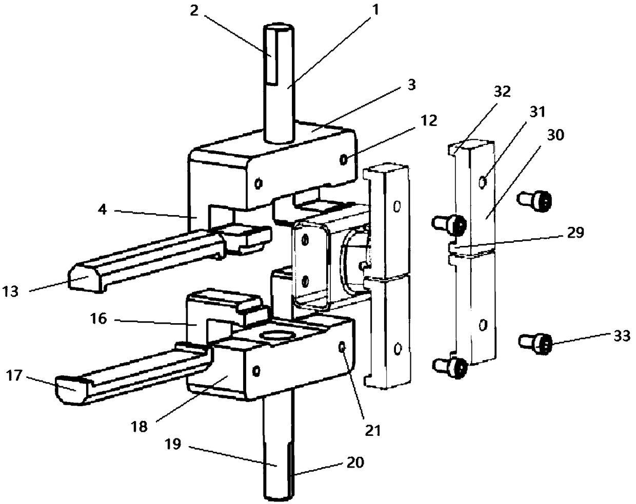
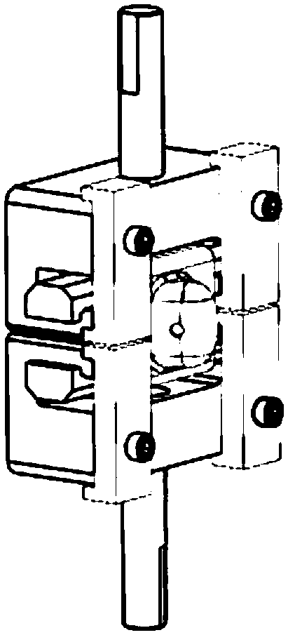
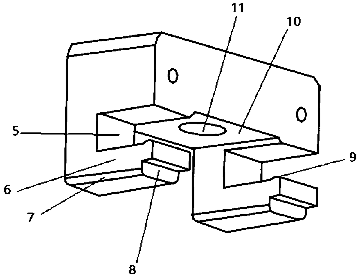
[0031] A drawing fixture for a rectangular tubular workpiece, the length of the workpiece to be measured is 20cm, the relative outer distance of the two first cantilevers is 35cm, the relative inner distance is 20.05cm, the distance between the top of the first tension seat and the lower part of the first groove is 30cm, the horizontal arm of the first cantilever is provided with a first chamfer along the width direction, and the gap between the first boss and the first vertical arm is 8.05cm. The relative outer distance of the two second cantilevers is 35cm, the relative inner distance is 20cm, the distance between the bottom of the second tension seat and the upper part of the second groove is 30cm, and the horizontal arm of the second cantilever is provided with a third chamfer along the width direction. The gap between the second boss and the second vertical arm is 8.05cm. Pass the first clamping block and the second clamping block through the through hole in the middle of...
Embodiment 2
[0033]A drawing fixture for a rectangular tubular workpiece, the length of the workpiece to be measured is 25cm, the relative outer distance of the two first cantilevers is 40cm, the relative inner distance is 25.05cm, the distance between the top of the first tension seat and the lower part of the first groove is 30cm, the horizontal arm of the first cantilever is provided with a first chamfer along the width direction, and the gap between the first boss and the first vertical arm is 10.05cm. The relative outer distance of the two second cantilevers is 40cm, the relative inner distance is 25.05cm, the distance between the bottom of the second tension seat and the upper part of the second groove is 30cm, and the horizontal arm of the second cantilever is provided with a third chamfer along the width direction , the gap between the second boss and the second vertical arm is 10.05cm. First, pass the first clamping block and the second clamping block through the through hole in t...
Embodiment 3
[0035] A drawing fixture for a rectangular tubular workpiece. The length of the workpiece to be measured is 30cm. The relative outer distance between two first cantilevers is 40cm, and the relative inner distance is 30.05cm. The horizontal arm of the first cantilever is provided with a first For chamfering, the gap between the first boss and the first vertical arm is 10cm. The relative outer distance of the two second cantilevers is 40cm, and the relative inner distance is 30.05cm. The horizontal arm of the second cantilever is provided with a third chamfer along the width direction, and the gap between the second boss and the second vertical arm is 10.05cm. First, pass the first clamping block and the second clamping block through the through hole in the middle of the workpiece to be tested. The side of the first clamping block without the first fixing groove is in contact with the inner surface of the upper part of the workpiece, and the second clamping block has no One sid...
PUM
 Abstract
Description
Claims
Application Information
 - R&D
- Intellectual Property
- Life Sciences
- Materials
- Tech Scout
- Unparalleled Data Quality
- Higher Quality Content
- 60% Fewer Hallucinations
Browse by: Latest US Patents, China's latest patents, Technical Efficacy Thesaurus, Application Domain, Technology Topic, Popular Technical Reports.
© 2025 PatSnap. All rights reserved.Legal|Privacy policy|Modern Slavery Act Transparency Statement|Sitemap|About US| Contact US: help@patsnap.com