Multi-rotor vehicle

A technology for a multi-rotor aircraft and an aircraft, applied in the field of aircraft, can solve the problems of short battery life, great influence by wind, small load capacity, etc., and achieve the effects of increasing battery life, improving battery life and reducing energy consumption.

Inactive Publication Date: 2019-01-25
FOSHAN SHENFENG AVIATION SCI & TECH
View PDF0 Cites 0 Cited by
  • Summary
  • Abstract
  • Description
  • Claims
  • Application Information

AI Technical Summary

Problems solved by technology

However, since multi-rotor aircraft are powered by batteries, and the total power consumption of multi-rotor aircraft is very large during use, multi-rotor aircraft powered by batteries generally have short battery life and small load capacity, which greatly limits the use of multi-rotor aircraft. performance and application areas
[0003] In order to overcome the shortcoming of the multi-rotor aircraft's short endurance time, various solutions have been proposed in the prior art: on the one hand, the fuel engine is used as the power, but the fuel engine cannot change the speed quickly, and the flexibility is limited; on the other hand, the balloon is used as the power. Auxiliary power, but the balloon auxiliary power is huge and is greatly affected by the wind; in addition, fuel cells are used as a power source, but the fuel cell technology is not mature enough to effectively solve the common problems of current multi-rotor aircraft

Method used


Image

  • Multi-rotor vehicle
  • Multi-rotor vehicle

Examples


Embodiment 1

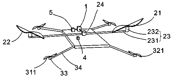
[0048] A multi-rotor aircraft, comprising: an engine 1, a power rotor mechanism, an attitude rotor mechanism, a storage battery 4 and a main frame 5;

[0049] The engine 1 generates power through the combustion of internal fuel;

[0050] The power rotor mechanism comprises a first power rotor 21, a second power rotor 22, a transmission shaft 23 and a differential gear 24; the first power rotor 21 and the second power rotor 22 are arranged symmetrically with respect to the central axis of the aircraft, and the first power rotor 21 and the second power rotor 22 have the same size, the first power rotor 21 is a positive paddle, and the first power rotor 21 is dynamically connected with the differential gear 24 through the transmission shaft 23; the second power rotor 22 is a reverse paddle, and the second power rotor 22 The transmission shaft 23 is power connected with the differential gear 24; the differential gear 24 is power connected with the engine 1, and the differential ge...

Embodiment 2

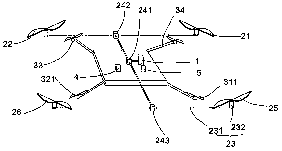
[0066] The multi-rotor aircraft includes: an engine 1, a power rotor mechanism, an attitude rotor mechanism and a storage battery 4.

[0067] The engine 1 generates power by combustion of internal fuel.

[0068] The power rotor mechanism includes a first power rotor 21 , a second power rotor 22 , a transmission shaft 23 , a differential gear 24 , a third power rotor 2 and a fourth power rotor 2 . The first power rotor 21 and the second power rotor 22 are symmetrically arranged with respect to the central axis of the aircraft. The first power rotor 21 and the second power rotor 22 are of the same size. The first power rotor 21 is a positive paddle. The shaft 23 is power connected; the second power rotor 22 is a reverse propeller, and the second power rotor 22 is power connected with the transmission shaft 23 . The third power rotor 2 and the fourth power rotor 2 are arranged symmetrically with respect to the central axis of the aircraft, the third power rotor 2 and the fourth ...


PUM


Abstract

The invention discloses a multi-rotor aircraft, which comprises an engine, a power rotor structure, an attitude rotor structure and a battery. The engine generates power by burning internal fuel. Thepower rotor structure comprises a power rotor and a transmission path, wherein the power rotor is dynamically connected with the engine through the transmission path; attitude rotor structure includesattitude rotor, attitude rotor motor and attitude rotor bracket. Attitude rotor is directly driven by attitude rotor motor. Attitude rotor is mounted on attitude rotor bracket. Attitude rotor motor is electrically connected with battery. The multi-rotor aircraft disclosed by the invention has the characteristics of long endurance time and high flexibility.

Description

technical field [0001] The present invention relates to the technical field of aircraft, and more specifically relates to a multi-rotor aircraft. Background technique [0002] At present, multi-rotor aircraft is an aircraft with simple structure, flexible control and stable flight attitude. Generally, there are different types such as four-axis, six-axis, and eight-axis. Thanks to the development of micro-electromechanical and sensor technologies in recent years, multi-rotor aircraft have been widely used in fields such as model aircraft and aerial photography platforms. However, since multi-rotor aircraft are powered by batteries, and the total power consumption of multi-rotor aircraft is very large during use, multi-rotor aircraft powered by batteries generally have short battery life and small load capacity, which greatly limits the use of multi-rotor aircraft. performance and application fields. [0003] In order to overcome the shortcoming of the multi-rotor aircraft...

Claims


Application Information

Patent Timeline
IPC IPC(8): B64C39/02B64C27/08B64D27/02B64D27/24B64D35/06
CPCB64C27/08B64C39/024B64D27/02B64D27/24B64D35/06B64D27/026Y02T50/60
Inventor 罗哲远王志成
Owner FOSHAN SHENFENG AVIATION SCI & TECH
Why Eureka
Try Eureka