Horizontal rotary position changer

A technology of horizontal rotation and positioner, which is applied in the direction of auxiliary devices, auxiliary welding equipment, welding/cutting auxiliary equipment, etc., and can solve the problems of easy entanglement or wear of cables, scrapping of parts, wear and other problems

Inactive Publication Date: 2019-01-25
大连河野智能装备有限公司
View PDF6 Cites 0 Cited by
  • Summary
  • Abstract
  • Description
  • Claims
  • Application Information

AI Technical Summary

Problems solved by technology

Due to the structural defects of the traditional horizontal rotary positioner, the layout of the control cables is relatively complicated. When the positioner performs horizontal rotation, various cables are easily entangled or worn, which affects the use of the positioner. longevity and reliability;
[0003] At the same time, the driving method of the traditional horizontal rotary positioner is that the motor or motor drives the reducer to drive the gear to rotate, the gear drives the toothed plate, and the toothed plate then drives the entire rotary box to rotate in the horizontal direction. There is a gap between the gear and the toothed plate Wear will occur during use, especially when there is an error in the dimensional accuracy of the gear and toothed plate, the above wear will be more serious, so the repeat positioning accuracy of the rotary positioner can be guaranteed, which will affect the welding quality. In severe cases, the setting will cause the entire Part scrapping or production line downtime

Method used


Image

  • Horizontal rotary position changer

Examples


Embodiment Construction

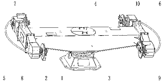
[0012] The specific implementation manner of the present invention will be described below with reference to the accompanying drawings. Such as figure 1 Shown: a horizontal rotary positioner, including a bottom box 1, a hollow reducer 2 is arranged above the bottom box 1, and the shell of the hollow reducer 2 is fixedly connected to the bottom of the center of the rotary box 3 , a rotary motor is arranged in the rotary box 3, the working end of the rotary motor is connected with the input end of the hollow reducer 2, and the output end of the hollow reducer 2 is fixed in the bottom box 1, and the hollow There is a gap between the housing of the reducer 2 and the bottom box 1, and an openable movable door 4 is provided on the upper part of the rotary box 3, and the movable door 4 is located above the chamber containing the rotary motor,

[0013] The two ends of the revolving box body 3 are respectively fixedly connected with a left support beam 5 and a right support beam 6, an...


PUM


Abstract

The invention discloses a horizontal rotary position changer. The horizontal rotary position changer is characterized by comprising a bottom box (1), a hollow speed reducer (2) is arranged above the bottom box (1), a shell of the hollow speed reducer (2) is fixedly connected with the bottom of the center position of a rotary box (3), and a rotary motor is arranged in the rotary box (3); an operating end of the rotary motor is connected with an input end of the hollow speed reducer (2), an output end of the hollow speed reducer (2) is fixed to the bottom box (1), and a gap is reserved between the shell of the hollow speed reducer (2) and the bottom box (1); the upper portion of the rotary box (3) is provided with an openable dodge gate (4) above a cavity in which the rotary motor is positioned.

Description

technical field [0001] The invention relates to the field of automatic welding, in particular to a horizontal rotary positioner. Background technique [0002] When using a welding robot to realize automatic welding, a positioner is required. Due to the structural defects of the traditional horizontal rotary positioner, the layout of the control cables is relatively complicated. When the positioner performs horizontal rotation, various cables are easily entangled or worn, which affects the use of the positioner. longevity and reliability; [0003] At the same time, the driving method of the traditional horizontal rotary positioner is that the motor or motor drives the reducer to drive the gear to rotate, the gear drives the toothed plate, and the toothed plate then drives the entire rotary box to rotate in the horizontal direction. There is a gap between the gear and the toothed plate Wear will occur during use, especially when there is an error in the dimensional accuracy ...

Claims


Application Information

Patent Timeline
Patent Type & Authority Applications(China)
IPC IPC(8): B23K37/047B23K37/00
CPCB23K37/00B23K37/047
Inventor 张学超傅亮刘文举
Owner 大连河野智能装备有限公司
Why Eureka
Try Eureka