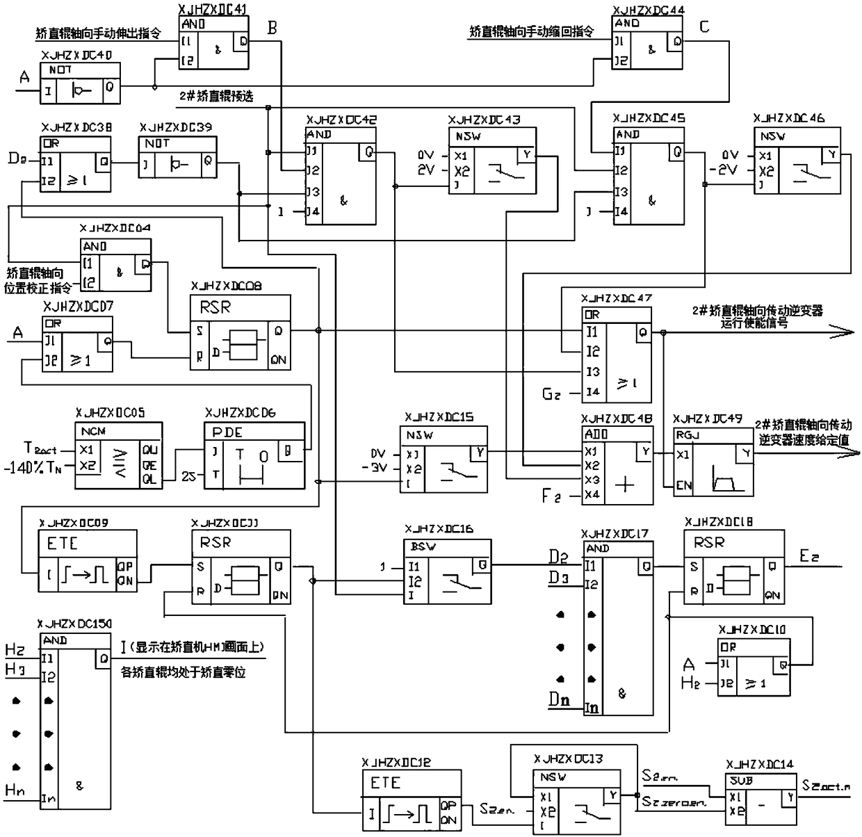
Control method for axial process straightening zero correction of straightening roller of shaped steel straightening machine

A technology for straightening and zero-position correction of a straightening machine, which is applied in the directions of comprehensive factory control, comprehensive factory control, program control, etc., which can solve the problems of poor straightening stability of rolling pieces, inability to achieve automatic axial zero position, and extreme influence on straightening quality. Large and other problems, to achieve the effect of high zero correction accuracy

Active Publication Date: 2019-01-18
MAANSHAN IRON & STEEL CO LTD
View PDF7 Cites 0 Cited by
  • Summary
  • Abstract
  • Description
  • Claims
  • Application Information

AI Technical Summary

Problems solved by technology

[0021] 1. The axial zero position of the straightening machine after the roll change cannot be realized automatically, and it can only be measured by manual wire drawing, which seriously affects the roll change time and delays production;
[0022] 2. During manual wire drawing measurement, due to the different wear and tear of the straightening roller sheets, the reference point is also different, which has a great impact on the straightening quality, especially the internal and external expansion of the flange after the rolling is difficult to control, including the rolled piece side bending, and poor straightening stability;
[0023] 3. There are unsafe problems during manual wire measurement, and there is no place for personnel to stand

Method used


Image

  • Control method for axial process straightening zero correction of straightening roller of shaped steel straightening machine
  • Control method for axial process straightening zero correction of straightening roller of shaped steel straightening machine
  • Control method for axial process straightening zero correction of straightening roller of shaped steel straightening machine

Examples


Embodiment Construction

[0042] The specific implementation of the present invention will be described in further detail below by describing the embodiments with reference to the accompanying drawings, so as to help those skilled in the art have a more complete, accurate and in-depth understanding of the inventive concepts and technical solutions of the present invention.

[0043] Such as figure 1 The structure of the present invention expressed is a section steel straightening machine. The section steel straightening machine includes nine cantilever type straightening rollers, four of which are upper straightening rollers, five are lower straightening rollers, and the upper and lower Arranged in a staggered manner, they are No. 1 straightening roll to No. 9 straightening roll (their numbers are R1 to R9); and N represents any one of No. 3 roll to No. 8 roll.

[0044] Among the nine straightening rollers, except that the axial positions of the R1 and R9 straightening rollers are fixed, the rest of the...


PUM


Abstract

The invention discloses a control method for axial process straightening zero correction of a straightening roller of a shaped steel straightening machine. The control program of the control method comprises the following six control units: axial mechanical zero correction unit of the No. 2 straightening roller; axial process straightening zero correction unit of the No. 2 straightening roller; axial manual adjustment control unit of the No. 2 straightening roller; axial process straightening zero correction unit of the No. n straightening roller; No. n straightening roller axial process straightening zero correction unit; and axial manual adjustment control unit of the No. n straightening roller. According to the control method for axial process straightening zero correction of the straightening roller of the shaped steel straightening machine, the problem existing in practical use of the straightening zero correction cylinder of the straightening process of the straightening roller of the large H-shaped steel straightening machine is solved, and the axial process straightening zero correction of the straightening roller is achieved without the zero correction cylinder and other zero correction detection device. Therefore the axial process straightening correction control method of the straightening roller is not only simple and reliable, but also has a high zero correction precision.

Description

technical field [0001] The invention belongs to the technical field of electric automation control of iron and steel industry production equipment. More specifically, the present invention relates to a control method for correcting the zero position of the axial process straightening of a straightening roller of a section steel straightening machine. Background technique [0002] The large H-beam production line of the Maanshan Iron and Steel Long Products Division adopts a cantilever-roller variable-pitch leveler to straighten H-beam rolled parts on-line. Rollers, five are the lower straightening rollers), arranged in a staggered manner up and down, numbered R1-R9 respectively. [0003] The schematic diagram of the arrangement of the straightening rollers of the section steel straightening machine is as follows: figure 1 shown. [0004] Among the nine straightening rollers, except that the axial positions of the R1 and R9 straightening rollers are fixed, the rest of the ...

Claims


Application Information

Patent Timeline
Patent Type & Authority Applications(China)
IPC IPC(8): G05B19/418B21D3/02
CPCB21D3/02G05B19/41865G05B2219/32252Y02P90/02
Inventor 叶光平张昱汪志远吴卫华包忠东朱旭光黄震王金来江卫华董长付潘利
Owner MAANSHAN IRON & STEEL CO LTD
Why Eureka
Try Eureka