Optical transceiver module with high coupling efficiency

An optical transceiver module, high-coupling technology, applied in the coupling of optical waveguides, light guides, optics, etc., can solve the problems of reduced optical fiber coupling efficiency, deformation and displacement, and reduced output optical power, and is easy to operate and facilitate mass production. , Simple and effective effect

Active Publication Date: 2019-01-18
THE 44TH INST OF CHINA ELECTRONICS TECH GROUP CORP
View PDF6 Cites 0 Cited by
  • Summary
  • Abstract
  • Description
  • Claims
  • Application Information

AI Technical Summary

Problems solved by technology

[0005] Therefore, our company releases the deformation stress through the laser spot welding of the first sleeve 11 and the second sleeve 12, such as figure 2 As shown, however, since the inside of the first sleeve 11 and the second sleeve 12 are C-shaped rings and ceramic cores, the release of deformation stress here will lead to deformation and displacement of the C-shaped rings and ceramic cores, resulting in reduced fiber coupling efficiency, The output optical power decreases, affecting the transmission of optical signals

Method used


Image

  • Optical transceiver module with high coupling efficiency
  • Optical transceiver module with high coupling efficiency
  • Optical transceiver module with high coupling efficiency

Examples


Embodiment approach

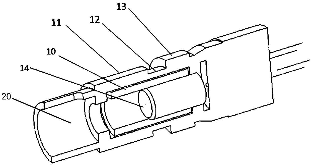
[0026] As a preferred embodiment, the inner diameter of the inner wall of the annular protrusion is 2.52 mm, the axial length of the C-shaped ring is 7 mm, the outer diameter of the ceramic core is 2.51 mm, the left end of the ceramic core and the inner wall of the annular protrusion are The gap length between the right ends is 6.05 mm.

[0027] It can be seen from Table 1 that by adopting the optical transceiver module with high coupling efficiency of the present invention, the yield rate of its production process is greatly improved.

[0028] Table 1 shows the yield comparison of products produced before and after adopting this improved method

[0029]

[0030]


PUM


Abstract

The invention belongs to the technical field of photoelectricity, and particularly relates to an optical transceiver module with the high coupling efficiency. The optical transceiver module comprisesan upper box board, a lower box board and a DIN type interface laser; a part of the DIN type interface laser is installed in a cavity formed by the upper box board and the lower box board, and the other part extends out of the cavity; the DIN type interface laser comprises a DIN type interface, a first sleeve, a second sleeve, a third sleeve, a ceramic core and a laser; the third sleeve, the second sleeve and the first sleeve are sequentially connected in a sleeved mode; the ceramic core is connected into the first sleeve, the second sleeve and the third sleeve in a sleeving mode; and the laser is located behind the ceramic core. According to the optical transceiver module, the multi-stage sleeves are adopted, and epoxy glue is used for performing reinforcement among the sleeves, so that astress of high-temperature deformation is released to a non-rigid joint between the laser and a circuit board through transmission, the influence of the external temperature on the output optical power of the optical transceiver module is avoided, and the output optical power is kept stable within a certain temperature range.

Description

technical field [0001] The invention belongs to the field of optoelectronic technology, in particular to an optical transceiver module with high coupling efficiency. Background technique [0002] The dual-fiber bidirectional surface-mount optical transceiver module is a transceiver-integrated optical module for high-speed data transmission. The maximum rate can reach 4.25Gbps. It has high requirements on the stability of the output optical power of the transmitter. The structure is as follows: figure 1 As shown, its working principle is: the external data signal is loaded to the laser of the DIN interface through the driver on the circuit board, and the electrical signal is converted into an optical signal at this time, and the optical signal enters the fiber core of the ceramic core through the light-emitting area of ​​the laser. After the external single-mode fiber is inserted into the DIN interface laser, it couples and aligns with the ceramic core through the alignment a...

Claims


Application Information

Patent Timeline
Patent Type & Authority Applications(China)
IPC IPC(8): G02B6/42
CPCG02B6/4255G02B6/4267
Inventor 席曼曼陈俊宇陈春霞丁鹏李冰贺燕吴广李欢
Owner THE 44TH INST OF CHINA ELECTRONICS TECH GROUP CORP
Why Eureka
Try Eureka