Ceiling lamp

A ceiling lamp and lamp panel technology, which is applied to lighting devices, fixed lighting devices, electric light sources, etc., can solve the problems of inconvenient disassembly, interference of lamp panel installation, troublesome operation, etc., so as to reduce the loss of power cords and facilitate fixed installation. Disk, easy and quick installation effect

Pending Publication Date: 2019-01-18
JINJIANG WONDERFUL PHOTOVOLTAIC LIGHTING
View PDF12 Cites 3 Cited by
  • Summary
  • Abstract
  • Description
  • Claims
  • Application Information

AI Technical Summary

Problems solved by technology

The operation is troublesome, and there are safety hazards at the same time. When replacing the LED ceiling lamp, it is inconvenient to disassemble. Often the power cord is cut directly, and then stripped to connect to the new lamp. However, the reserved length of the power cord is fixed. If there are too many, the power cord will not be enough and needs to be lengthened, which not only complicates the operation, but also further increases potential safety hazards.
[0005] (3) There is no concave cavity or groove on the lamp panel of the traditional ceiling lamp for accommodating the power cord connected to the LED ceiling lamp
Therefore, when fixing the lamp panel, it will not only interfere with the installation of the lamp panel, but also easily damage the insulation layer of the power cord during the installation process, and there is also a potential safety hazard

Method used


Image

  • Ceiling lamp
  • Ceiling lamp
  • Ceiling lamp

Examples


Embodiment Construction

[0031] In order to further explain the technical solution of the present invention, the present invention will be described in detail below through specific examples.

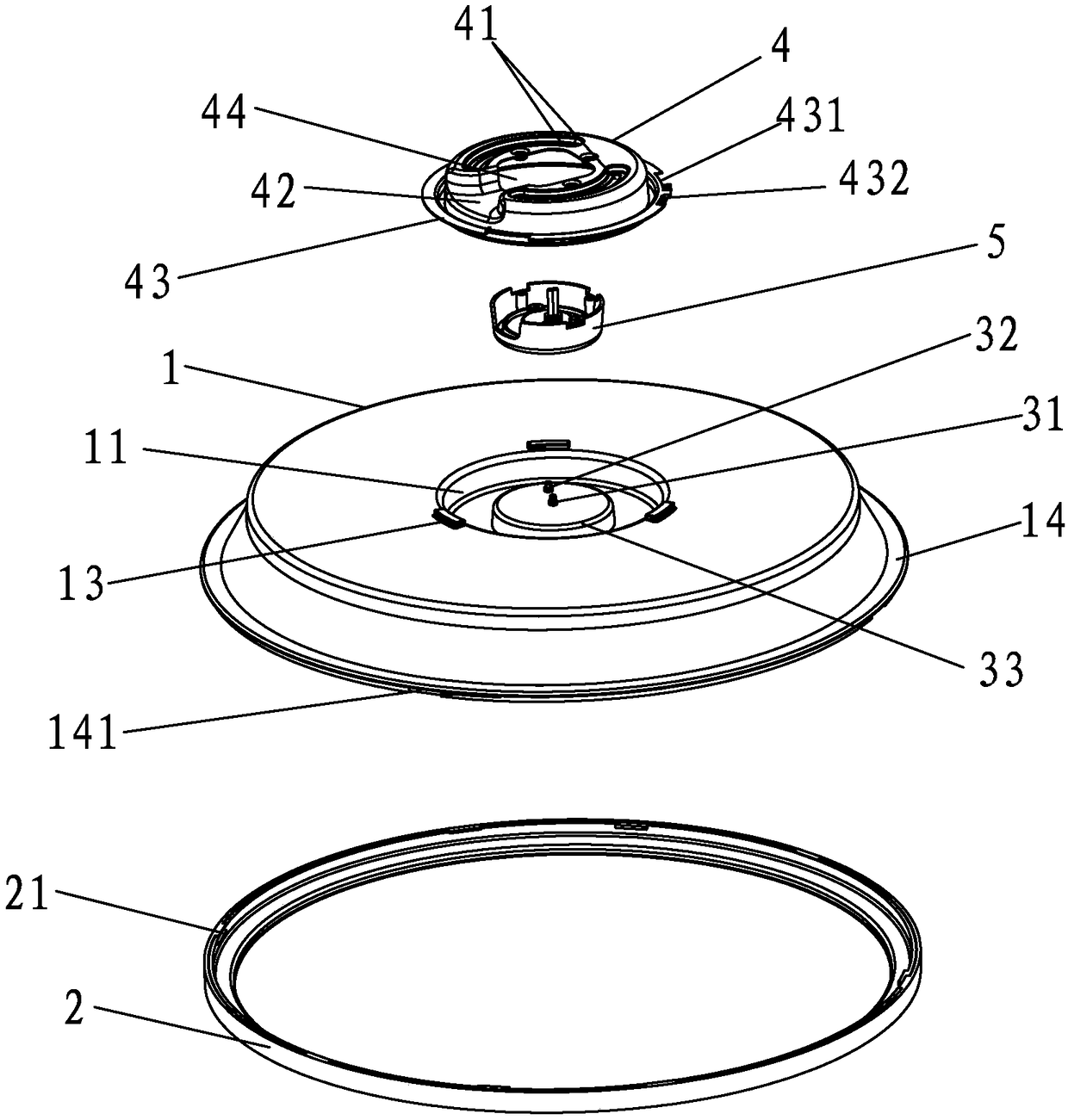
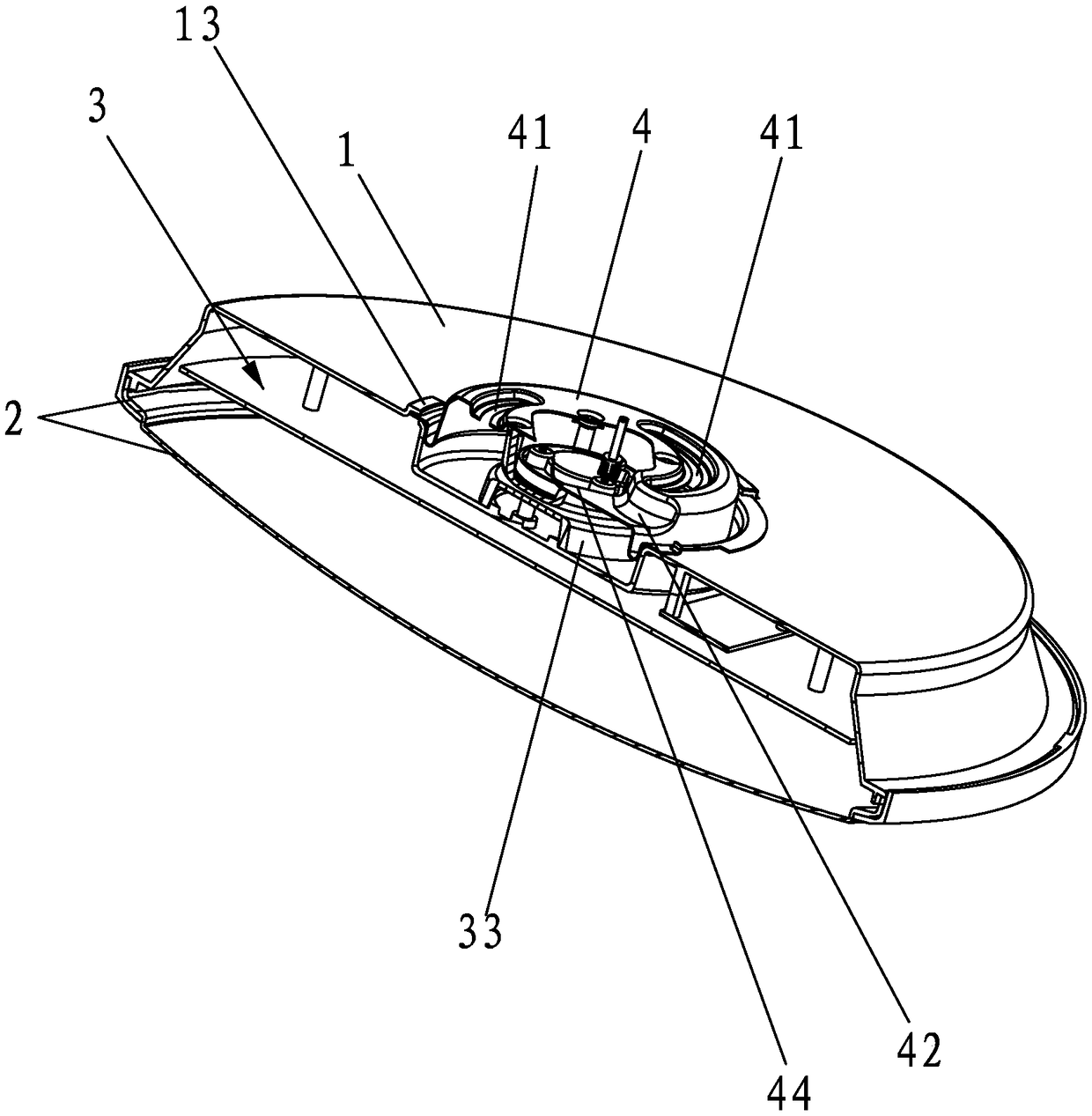
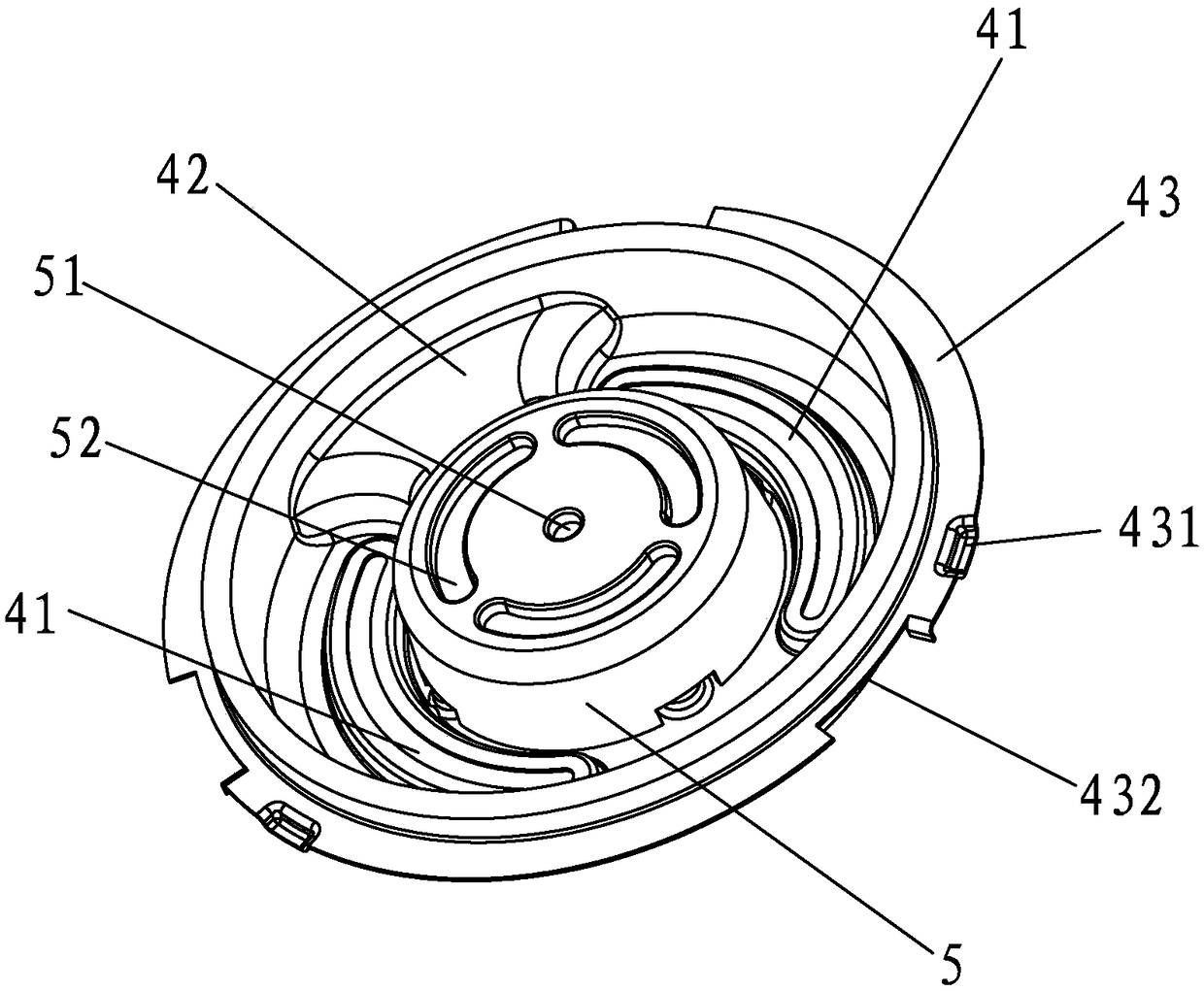
[0032] Such as Figure 1-3 As shown, the ceiling lamp of the present invention includes a lamp panel 1, a lampshade 2 and a light-emitting assembly 3, and also includes a mounting plate 4 and a lamp holder 5. The lamp holder 5 is installed on the mounting plate 4, and the lamp holder 5 A first metal contact piece 51 and a second metal contact piece 52 for connecting to a power line are provided (here, the first metal contact piece 51 and the second metal contact piece 52 are respectively connected to the indoor power line in a conventional manner, namely: The first metal contact piece 51 and the second metal contact piece 52 are respectively connected to the zero line and the fire of the indoor power line correspondingly), and at least two arc-shaped suspension holes 41 are provided on the mounting plate 4, and...


PUM


Abstract

The invention discloses a ceiling lamp. The ceiling lamp comprises a lamp panel, a lamp cover, a light-emitting assembly, an installing disc and a lamp holder, the lamp holder is installed on the installing disc, and a first metal contact piece and a second metal contact piece are arranged on the lamp holder; at least two arc hanging holes are formed in the installing disc, and the arc length of each hanging hole is greater than or equal to the perimeter of 1 / 4 of the installing disc; a groove part is formed in the installing disc, the installing disc and the lamp panel are provided with clamping structures, and an installing groove is formed in the lamp panel; the lamp panel is fixed to the installing disc in a rotary clamping mode, the installing disc is partially embedded in the installing groove, and the lamp cover and the lamp panel adopt separating installing structures; the light-emitting assembly is located between the lamp panel and the lamp cover and fixed to the lamp panel and comprises a light-emitting body, a first contact head and a second contact head, and the first contact head and the second contact head are correspondingly connected with the positive pole and thenegative pole of the light-emitting body. The ceiling lamp not only is simple in operation and convenient to dismantle, but also can eliminate the hidden safety danger caused by the wiring problem.

Description

technical field [0001] The invention relates to the technical field of lighting equipment, in particular to a ceiling lamp. Background technique [0002] Ceiling lamp is a kind of light fixture. As the name suggests, it is called ceiling light because the top of the light fixture is relatively flat and the bottom is completely attached to the roof when installed. At present, the most popular ceiling lamps on the market are LED ceiling lamps, which are often used in various places such as homes, offices, and entertainment venues. However, the existing ceiling lamps all have the following three deficiencies when installed: [0003] (1) The traditional way of installing ceiling lamps is to use a ladder to make installation holes on the top of the room, and then use expansion bolts to open the lamp panel and fix it on the top of the room. The screw holes are not well positioned to quickly align with the installation position, and the operation is inconvenient. During installat...

Claims


Application Information

Patent Timeline
Patent Type & Authority Applications(China)
IPC IPC(8): F21S8/04F21V23/06F21V17/10F21V17/16F21V17/12
CPCF21S8/04F21V17/10F21V17/12F21V17/164F21V23/06
Inventor 陈永威
Owner JINJIANG WONDERFUL PHOTOVOLTAIC LIGHTING
Why Eureka
Try Eureka