Paint roller with automatic feeding function

An automatic feeding and coating technology, which is applied in the direction of construction and building construction, can solve the problems of coating agglomeration, labor difficulty, heavy weight, etc., and achieve the effects of preventing coating agglomeration, reducing workload and simple structure

Inactive Publication Date: 2019-01-18
贵州省漆彩金州涂料有限公司
View PDF0 Cites 1 Cited by
  • Summary
  • Abstract
  • Description
  • Claims
  • Application Information

AI Technical Summary

Problems solved by technology

[0003] And now, there are some automatic feeding roller brushes, the paint is contained in the brush handle of the roller brush, and the paint is contained in the storage bucket for extraction, both of which have disadvantages. The paint makes the entire roller brush too heavy, which makes it difficult for workers to work. The second roller brush, with a large amount of paint in the storage tank, will cause the paint to agglomerate

Method used


Image

  • Paint roller with automatic feeding function
  • Paint roller with automatic feeding function
  • Paint roller with automatic feeding function

Examples


Embodiment Construction

[0039] The technical solutions in the embodiments of the present invention are clearly and completely described below in conjunction with the accompanying drawings. Apparently, the described embodiments are only a part of the embodiments of the present invention, not all of them.

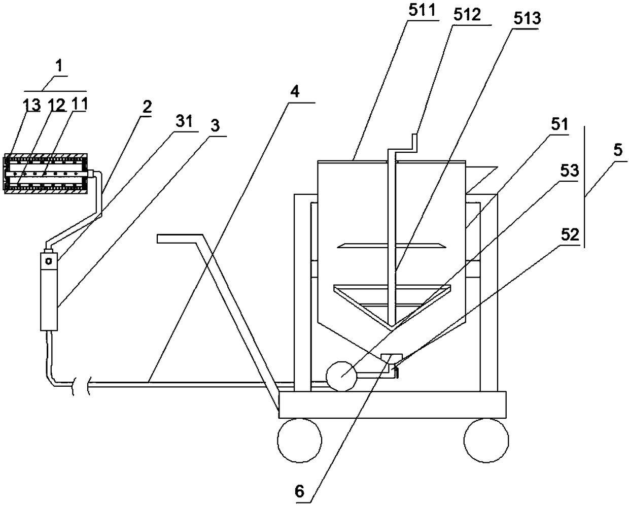
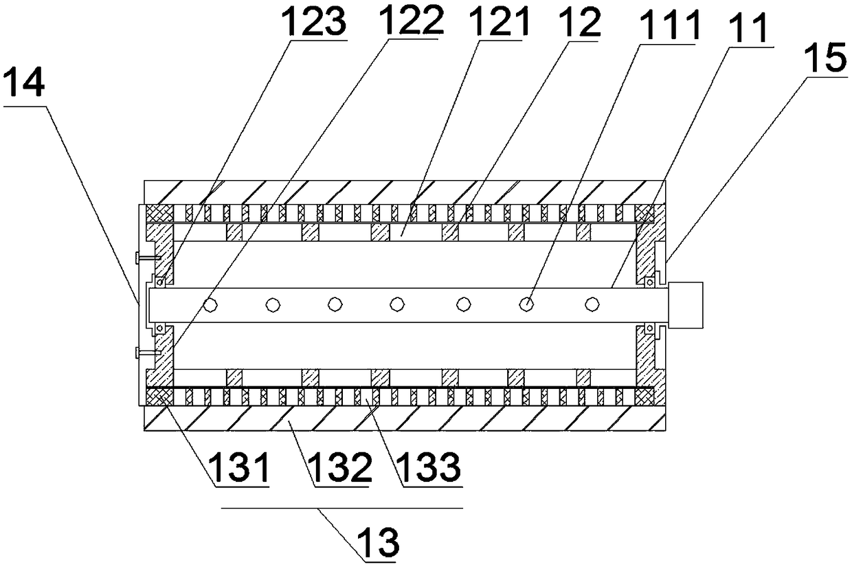
[0040] refer to Figure 1-4 , a paint roller for automatic feeding, including a roller brush 1, a connecting pipe 2, a telescopic rod 3, a feeding pipe 4 and a feeding device 5, and the roller brush 1 includes a shaft tube 11, an installation cylinder 12, a bristle cylinder 13, and a left end cover 14 And the right end cover 15, the left end of the shaft tube 11 is sealed, the installation tube 12 is rotatably installed on the outside of the shaft tube 11, the bristle tube 13 is detachably fixed on the outside of the installation tube 12, and the left end cover 14 is screwed At the left end of the installation cylinder 12, the right end cover 15 is embedded in the right end of the installation cylin...


PUM


Abstract

The invention relates to a paint roller with an automatic feeding function. The paint roller comprises a roller brush, a connecting pipe, a retractable rod, a material conveying pipe and a feeding device; the roller brush comprises a rotating shaft pipe, a mounting cylinder, a brush cylinder, a left end cover and a right end cover, the left end of the rotating shaft pipe is sealed, the mounting cylinder is rotatably disposed on the outer side of the rotating shaft pipe, the connecting cylinder is disposed on the outer side of the mounting cylinder, the left end cover is disposed at the left end of the mounting cylinder, and the right end cover is disposed at the right end of the mounting cylinder; multiple feeding holes are formed in the rotating shaft pipe; multiple first discharging holes are formed in the mounting cylinder; the feeding device comprises a material storage cylinder, a discharging pipe is arranged at the bottom of the material storage cylinder, and the lower end of thedischarging pipe is connected with a feeding pump. The connecting pipe is connected to the right end of the rotating shaft pipe, the hollow retractable rod is connected to the lower end of the connecting pipe, one end of the material conveying pipe penetrates through the retractable rod to be communicated with the connecting pipe, and the other end of the material conveying pipe is connect with an output end of the feeding pump.

Description

technical field [0001] The invention relates to the field of building decoration construction equipment, in particular to an automatic feeding paint roller. Background technique [0002] At present, in the interior decoration project, the rolling process of interior wall paint is all done manually, and the usually used paint rolling tool is a cylinder provided with a rolling brush head, on which a cylinder handle is housed. When rolling paint, the operator holds the handle of the roller, first dips the roller into the paint bucket to dip in the paint, then rolls the paint on the wall, dips in the paint and then rolls the wall again. Continuous rolling operation is not possible, and the work efficiency is low. , The labor intensity of the workers is high, and the thickness of the coating is uneven; and during the process of dipping the paint and rolling the roller, the paint slurry drips all over the floor, which not only wastes the paint, but also makes the floor and workers...

Claims


Application Information

Patent Timeline
Patent Type & Authority Applications(China)
IPC IPC(8): E04F21/08
CPCE04F21/08
Inventor 肖坤学李光明
Owner 贵州省漆彩金州涂料有限公司
Why Eureka
Try Eureka