
Cable maintenance lift truck

A lift truck and cable technology, applied in the direction of lifting devices, etc., can solve the problems of inconvenient movement, large space occupation, inconvenient operation, etc., and achieve the effects of improving maintenance efficiency, small space occupation, and simple structure.

Inactive Publication Date: 2019-01-18
STATE GRID CORP OF CHINA +1
View PDF9 Cites 3 Cited by
  • Summary
  • Abstract
  • Description
  • Claims
  • Application Information

AI Technical Summary

Problems solved by technology

[0002] Community streets in cities generally install various cables through poles. The height of the cables is usually relatively high, about 3 meters, which is much higher than the normal height of the human body. When repairing cables, maintenance personnel often need to use ladders or scaffolding, which is not safe and It is inconvenient to move; in the prior art, there is also a plan to use a vehicle lifting device to lift maintenance personnel. This device takes up a lot of space, has a wide swing range, is inconvenient to operate, and is easy to scratch other obstacles, causing damage, and it is difficult to move

Method used


Image

  • Cable maintenance lift truck
  • Cable maintenance lift truck

Examples


Embodiment 1

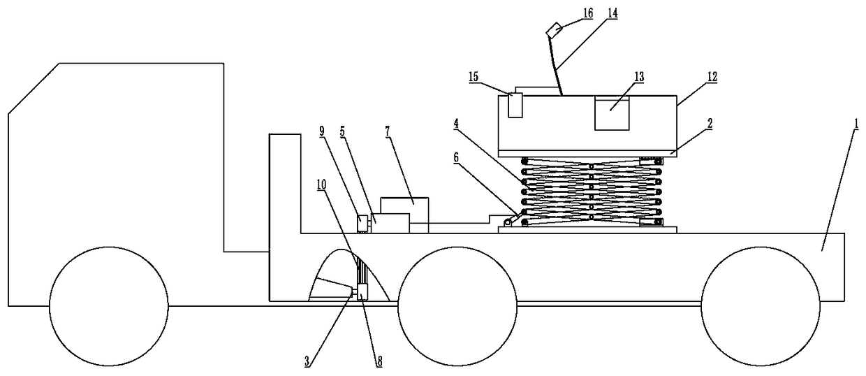
[0023] like figure 1 As shown, a kind of cable inspection and lifting vehicle comprises a truck 1, a lifting platform 2 installed on the truck 1, a lifting power device and a control system for driving the lifting platform 2 to move up and down, and the lifting power device is installed Between the lifting platform 2 and the truck 1, the control system controls and connects the lifting power device, and the power output shaft 3 of the truck 1 provides power to the lifting power device.

[0024] The lifting power device includes a scissor mechanism 4, a hydraulic oil pump 5, a hydraulic telescopic rod 6, a hydraulic oil valve and a hydraulic oil tank 7. The scissor mechanism 4 is composed of a plurality of scissor levers intersecting each other and hinged in the middle and at the end. The bottom ends of the first group of scissor rods at the bottom of the scissor mechanism 4 are hinged on the load-carrying platform of the truck 1, and the bottom ends of the second group of scis...

Embodiment 2

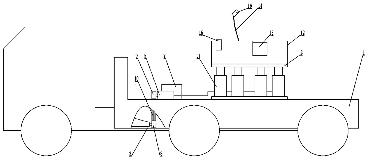
[0036] like figure 2 As shown, the difference from Embodiment 1 is that the lifting power device includes several hydraulic telescopic columns 11, hydraulic oil pumps 5, hydraulic oil valves and hydraulic oil tanks 7, and each of the hydraulic telescopic columns 11 is vertically installed on the truck 1 The bottom of the lifting platform 2 is installed on the top of each hydraulic telescopic column 11, the hydraulic oil pump 5 drives each hydraulic telescopic column 11 to expand and contract up and down through the hydraulic oil circuit, and the hydraulic oil valve is installed In the hydraulic oil circuit between the hydraulic oil pump 5 and the hydraulic telescopic column 11 , the hydraulic oil tank 7 provides hydraulic oil to the hydraulic oil pump 5 .

[0037] The hydraulic telescopic column 11 can replace the scissor mechanism and the hydraulic telescopic rod 6 to make the lifting platform 2 vertically lift.


PUM


Abstract

The invention relates to the technical field of power maintenance equipment, in particular to a cable maintenance lift truck. The cable maintenance lift truck includes a carrying truck, a lifting platform mounted on the carrying truck, a lifting power device for driving the lifting platform to move up and down and a control system, the lifting power device is mounted between the lifting platform and the lift truck, the control system controls and is connected with the lifting power device, and a power output shaft of the carrying truck provides power for the lifting power device. The cable maintenance lift truck has the advantages of scientific design, simple structure, small occupied space, convenient and fast performance, safe and stable performance and improved maintenance efficiency.

Description

technical field [0001] The invention relates to the technical field of electric power maintenance equipment, in particular to a cable maintenance lifting vehicle. Background technique [0002] Community streets in cities generally install various cables through poles. The height of the cables is usually relatively high, about 3 meters, which is much higher than the normal height of the human body. When repairing cables, maintenance personnel often need to use ladders or scaffolding, which is not safe and It is inconvenient to move; in the prior art, there is also a plan to use a vehicle lifting device to lift maintenance personnel. This device takes up a lot of space, has a wide swing range, is inconvenient to operate, easily scratches other obstacles, causes damage, and is difficult to move. [0003] In order to solve the above existing problems, people have been seeking an ideal technical solution. Contents of the invention [0004] The purpose of the present invention ...

Claims


Application Information

Patent Timeline
IPC IPC(8): B66F11/04B66F13/00
CPCB66F11/04B66F11/042B66F13/00
Inventor 王磊夏兰万彦王萍张超杨冬冬谢磊曾臻陈磊张磊黄超
Owner STATE GRID CORP OF CHINA
Learn More