
Method for obtaining ventricular pacing threshold of implantable cardiac pacemaker

A cardiac pacemaker and pacing threshold technology, which is applied in the field of medical devices, can solve problems such as adverse consequences of patients, interference of test results, and wrong recognition of loss and capture, so as to avoid hidden dangers of test result errors, avoid test result errors, and algorithm simplified effect

Active Publication Date: 2019-01-18
SHAANXI QINMING MEDICAL CO LTD
View PDF6 Cites 5 Cited by
  • Summary
  • Abstract
  • Description
  • Claims
  • Application Information

AI Technical Summary

Problems solved by technology

[0004]However, the R wave generated by the own ventricular activation may interfere with the test results, and even cause the pacemaker to measure the wrong ventricular pacing threshold, resulting in the output pulse Failure to capture the ventricle, with serious adverse consequences for the patient
For example, in VVI mode, the pacemaker has no sense of atrial events, but if the patient has its own atrioventricular conduction (ie, AS-VS), then, when the test pacing pulse VP cannot capture the ventricle, the collected ER wave The data may include both the ER wave of the test pacing pulse VP and the R wave of the own ventricular excitation; another example, in the DDD mode, when the own atrioventricular conduction is fast (the AS-VS interval is about 100ms), the same , if the test pacing pulse VP fails to capture the ventricle, the collected ER wave data may include both the ER wave of the test pacing pulse VP and the R wave of its own ventricular activation
In both cases, the pacemaker may misidentify loss of capture as capture, resulting in a lower measured ventricular threshold than the actual value
When the pacemaker resets the ventricular pulse amplitude based on the wrong threshold, the pacemaker may continue to deliver pulses that do not capture the ventricle, with serious consequences

Method used


Image

  • Method for obtaining ventricular pacing threshold of implantable cardiac pacemaker
  • Method for obtaining ventricular pacing threshold of implantable cardiac pacemaker
  • Method for obtaining ventricular pacing threshold of implantable cardiac pacemaker

Examples


Embodiment Construction

[0024] The present invention is described in further detail below in conjunction with accompanying drawing:

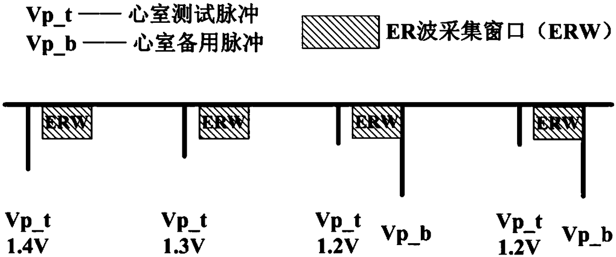
[0025] Figure 1a is the expected effect of the prior art in the threshold testing process: a) during the ventricular pacing threshold search process, send out the ventricle test pulse, and collect the ER wave data of the corresponding test pulse in the ER wave acquisition window, and then capture the ER wave data with the standard Compare the ER wave with the lost ER wave data to determine the capture state of the current test pulse; b) Gradually reduce the amplitude of the ventricular test pulse, and confirm the capture state in turn; c) When confirming a certain amplitude of the ventricular test pulse If the ventricle cannot be captured, a backup pulse will be issued immediately; d) When the pulse of the same amplitude is lost twice, the ventricular pacing threshold is determined to be "test amplitude + 0.1V", and the ventricular pacing pulse amplitude is reset accor...


PUM


Abstract

The invention discloses a method for obtaining the ventricular pacing threshold of an implantable cardiac pacemaker, which comprises the following steps: 1) switching the pacemaker from a current modeto a VDI mode, and then collecting VV intervals and corresponding AS-VS interval value, and then according to the VV interval and its corresponding AS-The mean ventricular rate and the mean atherosclerosis rate were calculated by VS interval. VS interval; 2) set that frequency of ventricular test pulse to mean ventricular rate + 10bpm, and set the t mask window after AS event to mean AS-VS interval + 50ms; 3) that t pulse VP is discharged accord to the average ventricular rate +10 bpm, the ER wave is acquire, The ventricular pacing threshold of the implantable cardiac pacemaker is confirmed by the collected ER wave. During this period, when the ventricular test pulse appears in the test shield window, the interval pause threshold test is performed, and the pulse amplitude is set as the programmable amplitude. The method can obtain the ventricular pacing threshold of the implantable cardiac pacemaker more accurately.

Description

technical field [0001] The invention belongs to the technical field of medical devices, and relates to a method for obtaining a ventricular pacing threshold of an implantable cardiac pacemaker. Background technique [0002] Since the first cardiac pacemaker was implanted in the human body in 1958, after 60 years of development, various physiological automatic functions have been continuously integrated into the pulse generator, which has significantly improved sinus bradycardia, third-degree atrioventricular Symptoms of patients such as conduction block, and effectively improved their quality of life. Among them, ensuring the effective pacing of the heart is the most basic purpose and the most important function of the implantable cardiac pacemaker. Especially safe and reliable ventricular pacing will be directly related to the life safety of patients. [0003] The ER wave is a depolarization wave triggered by pulse stimulation of ventricular myocytes, which can be used as...

Claims


Application Information

Patent Timeline
IPC IPC(8): A61N1/365
CPCA61N1/365A61N1/36592
Inventor 任江波陈小龙朱妙娜
Owner SHAANXI QINMING MEDICAL CO LTD
Learn More