Implant recycling apparatus and application and packaging thereof
A technology for implants and packaging containers, which is used in prostheses, filters in blood vessels, medical science, etc., can solve the problems of high success rate of implant recovery, stuck or stuck, low operation difficulty, etc., and achieves improved recovery. Success rate, easy recovery operation, and the effect of reducing experience and technical requirements
- Summary
- Abstract
- Description
- Claims
- Application Information
AI Technical Summary
Problems solved by technology
Method used
Image

Examples
Embodiment 1
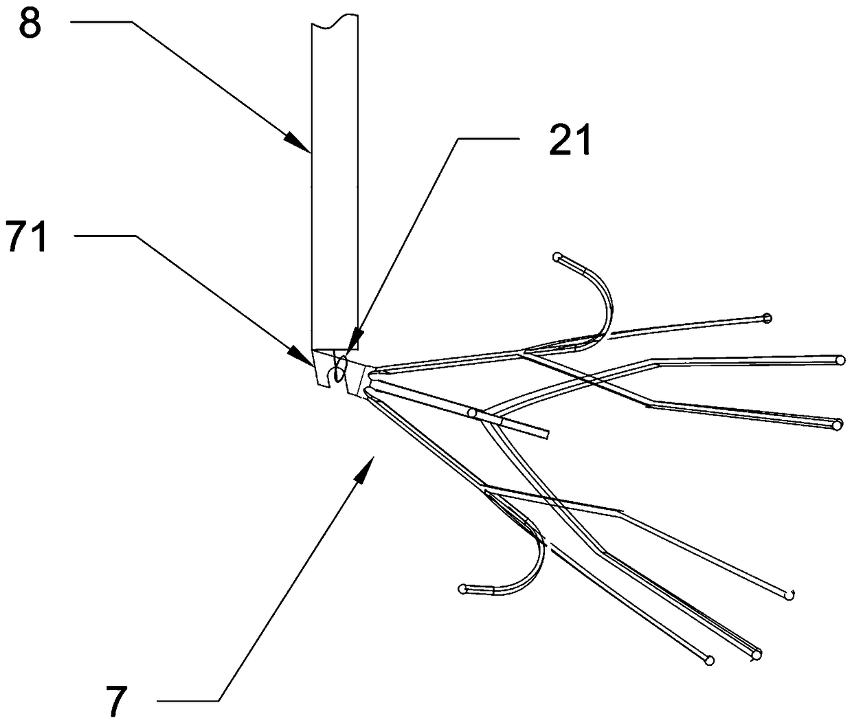
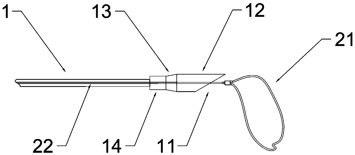
[0083] An implant grabber, see image 3 or Figure 4 , which includes a recovery sheath 1 and a capture unit 2, the capture unit 2 is slidably arranged in the recovery sheath 1 relative to the recovery sheath 1, and is configured to be able to be pushed and pulled in and out for recovery The distal end of the sheath 1 is used to catch the implant 7 , and the distal end of the recovery sheath 1 is an oblique opening 11 .
[0084] Wherein, the angle of the oblique opening 11 can be set as a fixed angle according to needs, so as to help guide the whole or part of the implant into the recovery sheath 1 . When the implant is partially introduced into the recovery sheath 1 , the whole implant tends to be parallel to the distal lumen of the recovery sheath 1 . The angle of the bevel 11 can be defined as the angle β between the port slope of the bevel 11 and the central line of the distal tube axis of the recovery sheath 1, see Figure 9 and Figure 10 , the pipe wall at the incli...
Embodiment 2
[0088] This embodiment provides a preferred implementation of the capture unit of the implant capture device in the foregoing embodiment 1.
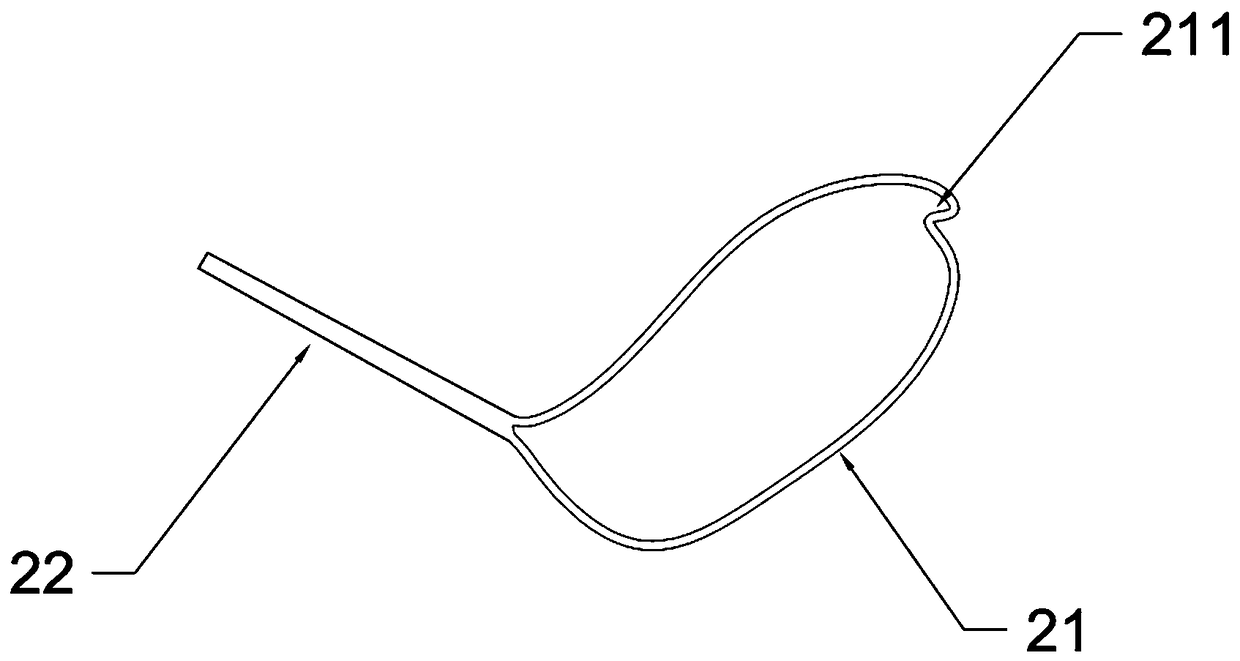
[0089] see image 3 and Figure 4 , the capture unit 2 of this embodiment includes a ferrule 21 and a rod 22 connected thereto, wherein the rod 22 is configured to be able to push and pull the ferrule 21 into and out of the distal port of the recovery sheath 1, that is, the oblique opening 11 , to capture and pull the implant.
[0090] Generally, the ferrule 21 can be selected to have one or more elastically deformable metal annular parts. As an optional embodiment, the ferrule 21 is arranged to have a plurality of annular parts, and each annular part is connected to the distal end of the rod 22 and uniformly distributed outward with the rod 22 as the center. The inner core of the ferrule 21 can be formed by twisting multiple strands of metal wires, and the toughness and strength of the ferrule 21 can be controlled by the wire diamete...
Embodiment 3
[0097] On the basis of the foregoing embodiment 1 and / or embodiment 2, this embodiment further provides an implant grabber. The implant catcher assembly in this embodiment also includes a sheath seat 3 and / or a hemostatic valve, which can improve the safety and operability of the operation.
[0098] see Figure 5 , Figure 6 , the proximal end of the recovery sheath tube 1 of the implant grabber shown in it is provided with a sheath seat 3 and a first hemostatic valve 4, and the first hemostatic valve 4 and the sheath seat 3 are detachably sealed by a sealing connector at one end connect. The sheath seat 3 and the recovery sheath tube 1 may be of an integral structure, or may be of a detachable connection structure. One end of the sheath seat 3 communicates with and seals the proximal end of the recovery sheath tube 1 , and the hemostatic valve communicates with the recovery sheath tube 1 through the sheath seat 3 . The first hemostatic valve 4 prevents the patient's blood...
PUM
 Abstract
Description
Claims
Application Information
 - R&D
- Intellectual Property
- Life Sciences
- Materials
- Tech Scout
- Unparalleled Data Quality
- Higher Quality Content
- 60% Fewer Hallucinations
Browse by: Latest US Patents, China's latest patents, Technical Efficacy Thesaurus, Application Domain, Technology Topic, Popular Technical Reports.
© 2025 PatSnap. All rights reserved.Legal|Privacy policy|Modern Slavery Act Transparency Statement|Sitemap|About US| Contact US: help@patsnap.com