Method and system for use in dynamometer testing of a motor vehicle

A technology for dynamometers and vehicles, which is applied in the direction of vehicle testing, engine testing, machine/structural component testing, etc. It can solve the problems of increased complexity of vehicle transmissions, save time and energy, and reduce the time for setting tests Effect

Active Publication Date: 2019-01-15
ROTOTEST INT
View PDF9 Cites 2 Cited by
  • Summary
  • Abstract
  • Description
  • Claims
  • Application Information

AI Technical Summary

Problems solved by technology

The increased complexity of vehicle transmissions presents corresponding challenges for dynamometer test systems

Method used


Image

  • Method and system for use in dynamometer testing of a motor vehicle
  • Method and system for use in dynamometer testing of a motor vehicle
  • Method and system for use in dynamometer testing of a motor vehicle

Examples


Embodiment Construction

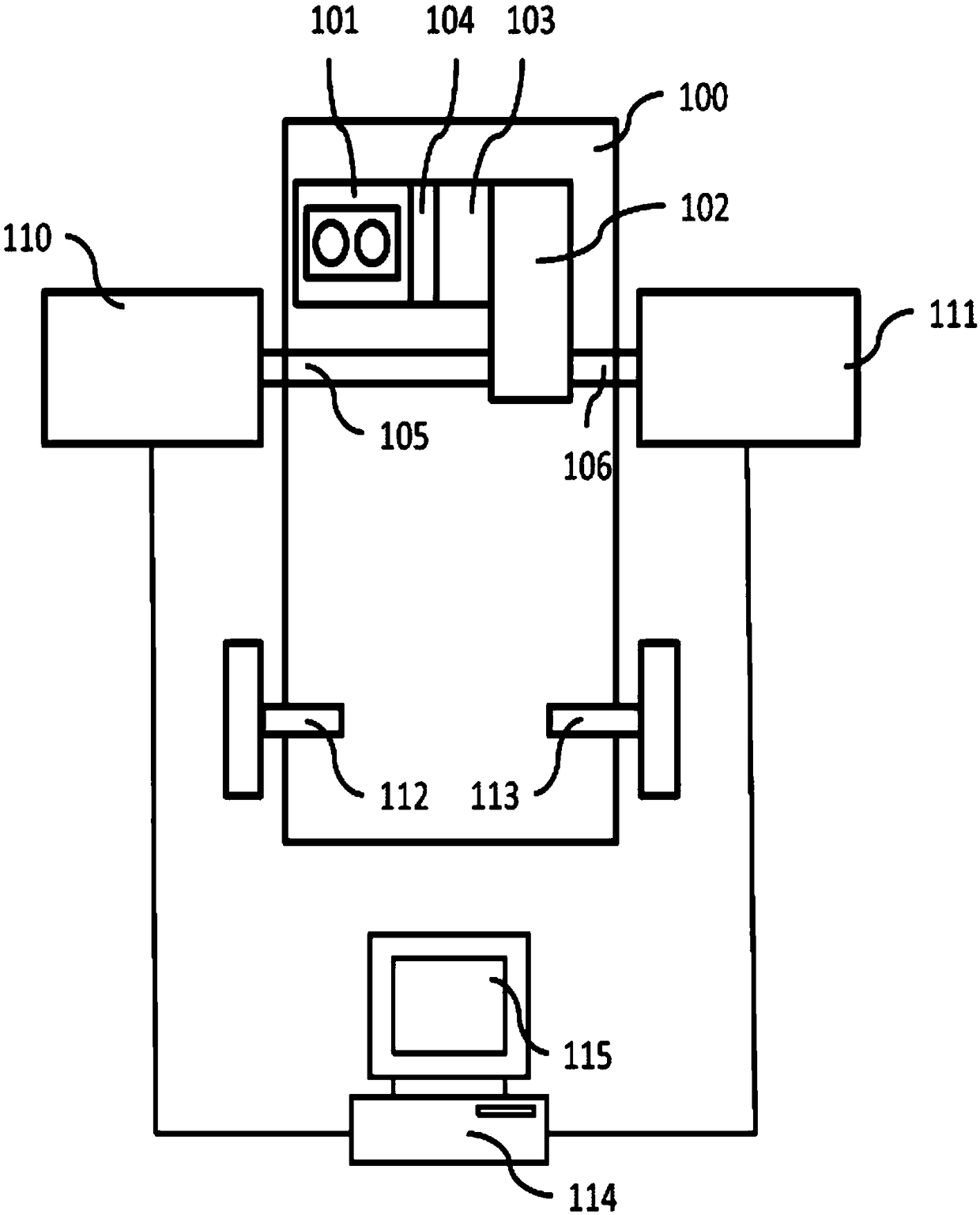
[0035] figure 1 A vehicle 100 is disclosed which is configured for testing according to the vehicle dynamometer system of the present invention.

[0036] Vehicle 100 is a two-wheel drive vehicle and includes front axle axles, or half axles 105 , 106 , and rear axle axles 112 , 113 . The wheels of the vehicle 100 are not shown as the vehicle is set up for dynamometer testing.

[0037] The vehicle 100 of the present disclosure includes a powertrain including a power source such as an internal combustion engine 101 connected to a gearbox 102 . Gearbox 102 may be of any suitable type, for example consisting of a manual transmission or an automatic transmission. Front axle (half) axles 105 , 106 extend from the gearbox to the front axle wheels of the vehicle 100 .

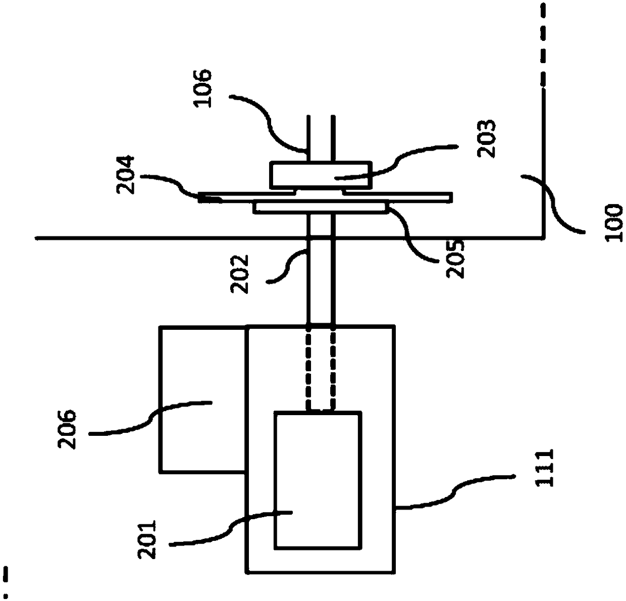
[0038] A vehicle dynamometer system is connected to the vehicle 100 and includes dynamometer test units 110 , 111 . The dynamometer test units 110, 111 are connected to a measurement and control system 114, e.g. a c...


PUM


Abstract

The present invention relates to a vehicle dynamometer system for dynamometer testing of a vehicle (100), comprising at least one dynamometer test unit (110, 111) having a power source (201), the power source (201) comprising an output shaft (202) arranged for, in use, rotation with a vehicle wheel shaft (105, 106), the system further comprising an adapter plate, said adapter plate comprising means for allowing fixed connection to a wheel hub (203) of a wheel shaft (105, 106) being tested, said adapter plate further comprising means for allowing fixed connection of the adapter plate to the output shaft (202) of said dynamometer test unit (110, 111) to thereby connect the output shaft (202) of the dynamometer test unit (110, 111) to said wheel shaft (105, 106). The adapter plate (204) is designed such that, when fixedly connected to said wheel hub (203) but disconnected from said dynamometer test unit (110, 111), said adapter plate (204) is arranged to support the vehicle (100) to allowrelocation of said vehicle (100) while supported by said adapter plate (204).

Description

technical field [0001] The present invention relates to dynamometer testing of vehicles and in particular to a method for use when dynamometer testing a vehicle having at least one axle and a power source for applying power to said first axle. Background technique [0002] Dynamometer testing of vehicles is known per se and can be performed, for example, by a roller (rolling road) dynamometer equipped with large rollers supporting the wheels, and is used to apply braking Torque is applied to the drive wheels of the vehicle. However, such systems do not always provide the required measurement accuracy and / or measurement degrees of freedom. [0003] Another vehicle dynamometer system for vehicle dynamometer testing is disclosed in US Patent 4,669,318 (Angstrom). This application relates to a device for dynamometer testing of vehicles, wherein a load absorbing device in the form of a hydrostatic pump assembly has an input shaft for engagement with a driven wheel shaft of the ...

Claims


Application Information

Patent Timeline
Patent Type & Authority Applications(China)
IPC IPC(8): G01M17/007G01M15/00G01M17/00
CPCG01M15/044G01M17/007G01M15/00G01M17/00G01M17/0072G01M17/0074G01L3/20
Inventor 尼尔斯·G·恩斯特伦约翰·费恩隆德克里斯蒂安·恩斯特伦
Owner ROTOTEST INT
Why Eureka
Try Eureka