A reverse modulation device and method based on micromirror array structure

A reverse modulation and micromirror array technology, applied in electrical components, electromagnetic wave transmission systems, transmission systems, etc., can solve the problems of low modulation rate, low modulation contrast, low modulation contrast, etc., and achieve high modulation efficiency, rapid feedback, The effect of large flip angle

Active Publication Date: 2021-03-02
ACAD OF OPTO ELECTRONICS CHINESE ACAD OF SCI
View PDF4 Cites 0 Cited by
  • Summary
  • Abstract
  • Description
  • Claims
  • Application Information

AI Technical Summary

Problems solved by technology

The out-of-focus reverse modulator is relatively simple and easy to implement, but the disadvantage is that the modulation contrast is not high and the modulation rate is low
[0006] The electroabsorption modulation based on the cat's eye effect is to place an electroabsorption optical modulator on the focal plane of the cat's eye optical system, and realize the absorption / reflection of the incident light focused on the focal plane through the driving circuit, so as to control the reverse modulation terminal echo state to characterize the For the transmitted information, electro-absorption reverse modulation also has the problem of low modulation contrast

Method used


Image

  • A reverse modulation device and method based on micromirror array structure
  • A reverse modulation device and method based on micromirror array structure
  • A reverse modulation device and method based on micromirror array structure

Examples


Embodiment Construction

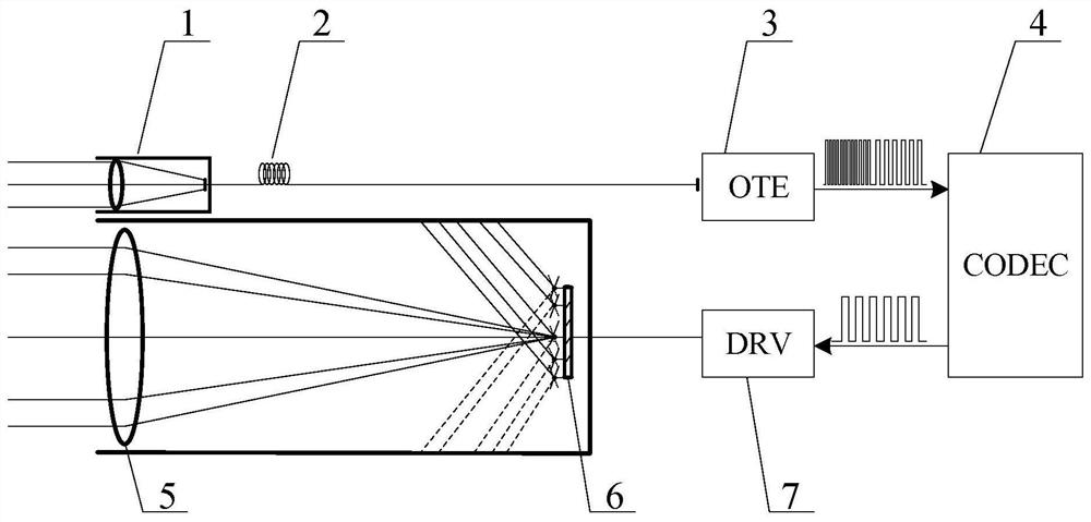
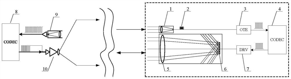
[0031] The present invention provides a reverse modulation device based on a micromirror array structure, including a receiving device 1, a first photoelectric converter 3, a first codec 4, a cat's eye device 5, a micromirror array 6 and a driver 7, wherein: receiving The device 1 receives the query light and transmits the query light to the first photoelectric converter 3, the first photoelectric converter 3 converts the optical signal into an electrical signal, the first codec 4 encodes the electrical signal to generate a time sequence code, and The time-series code is sent to the driver 7; the cat's eye device 5 receives the modulated light and converges the modulated light to the micromirror array 6, and the driver 7 drives the reflective micromirror in the micromirror array 6 to rotate according to the time-sequence code, so that the modulated light is reflected Back to the original direction.

[0032] In order to make the object, technical solution and advantages of the ...


PUM


Abstract

The invention provides a reverse modulation device based on a micromirror array structure, comprising a receiving device (1), a first photoelectric converter (3), a first codec (4), a cat's eye device (5), and a micromirror array (6) and a driver (7), wherein the receiving device (1) receives the query light and transmits the query light to the first photoelectric converter (3), and the first photoelectric converter (3) converts the optical signal into an electrical signal , the first codec (4) encodes the electrical signal to generate a time-series code, and sends the time-sequence code to the driver (7); the cat's eye device (5) receives the modulated light and converges the modulated light to the micromirror array ( 6), the driver (7) drives at least one reflective micromirror in the micromirror array (6) to rotate according to the time sequence code, so as to reflect the modulated light back to the original direction. On the other hand, the present invention also provides a reverse modulation method based on the micromirror array structure.

Description

technical field [0001] The invention relates to the field of laser recognition response and reverse modulation, in particular to a reverse modulation device and method based on a micromirror array structure. Background technique [0002] The use of optical reverse modulation technology for wireless optical communication has developed rapidly in recent years. Laser identification response devices using the principle of reverse light modulation can be divided into reflective modulation based on corner reflectors and transmissive modulation based on the cat's eye effect according to different modulation methods. Modulation methods such as defocus modulation and electroabsorption modulation have their own characteristics as follows. [0003] The reflective modulator based on the corner reflector realizes reverse modulation by setting a reflective structure on the reflective surface of the corner reflector and changing the reflection characteristics of the reflective surface. Bo...

Claims


Application Information

Patent Timeline
Patent Type & Authority Patents(China)
IPC IPC(8): H04B10/50H04B10/516
CPCH04B10/503H04B10/5057H04B10/516
Inventor 李锋朱精果姜成昊刘汝卿蒋衍叶征宇
Owner ACAD OF OPTO ELECTRONICS CHINESE ACAD OF SCI
Why Eureka
Try Eureka