
A Calibration Method of Attitude Angle Error of Dual-axis Rotary Inertial Navigation System

An inertial navigation system and dual-axis rotation technology, applied in the field of inertial navigation, can solve the problem of increasing attitude error, reduce the impact and improve the attitude accuracy of the system

Active Publication Date: 2022-06-24
昆山天地睿航智能科技有限公司
View PDF10 Cites 0 Cited by
  • Summary
  • Abstract
  • Description
  • Claims
  • Application Information

AI Technical Summary

Problems solved by technology

However, due to the introduction of the rotating mechanism, many errors become the source of the cone error, which in turn leads to an increase in the attitude error

Method used


Image

  • A Calibration Method of Attitude Angle Error of Dual-axis Rotary Inertial Navigation System
  • A Calibration Method of Attitude Angle Error of Dual-axis Rotary Inertial Navigation System
  • A Calibration Method of Attitude Angle Error of Dual-axis Rotary Inertial Navigation System

Examples


Embodiment Construction

[0064] The technical solutions protected by the present invention will be described in detail below with reference to the accompanying drawings.

[0065] The attitude angle error calibration method proposed by the present invention is suitable for general platform-type inertial navigation systems, and most of the general platform-type inertial navigation systems adopt a two-frame three-axis structure, that is, a gyroscope, an accelerometer, an outer frame, an inner frame and a platform The gyroscope and the accelerometer are mounted on the platform platform, and the outer frame, the inner frame and the platform platform can rotate around the outer ring axis, the inner ring axis and the platform body axis respectively.

[0066] A method for calibrating an attitude angle error of a dual-axis rotary inertial navigation system, comprising the following steps:

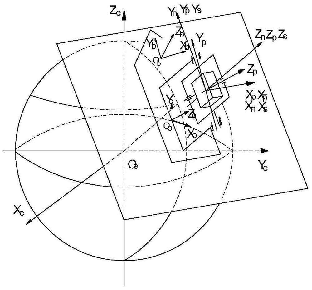
[0067] Step 1: Construct the coordinate system, figure 1 A schematic diagram of each coordinate system constructed by th...


PUM


Abstract

The present invention proposes a method for calibrating the attitude angle error of the dual-axis rotary inertial navigation system. By constructing multiple coordinate systems, the installation deviation between the shaft system of the IMU installed on the inner frame and the inner ring shaft and the outer ring shaft is calculated. Angle, that is, the roll misalignment angle is calibrated out, which reduces the influence of the cone error angle on the system attitude; at the same time, the non-orthogonal angle between the rotation axes and the swing angle of the axis itself are calibrated by the Kalman filter method, and the 16-position rotation is used Observation information and navigation data in the process of Kalman filtering are obtained by using the method, which further improves the attitude accuracy of the system and the long-term navigation accuracy of the system.

Description

technical field [0001] The invention relates to the field of inertial navigation, in particular to a method for calibrating attitude angle errors of a dual-axis rotary inertial navigation system. Background technique [0002] Dual-axis rotary inertial navigation is a navigation technology that has emerged in China in recent years. Due to the maturity and wide application of laser gyroscope technology, the continuous improvement of the performance of fiber optic gyroscope makes the optical gyroscope can use modulation technology. Within the navigation coordinate system, modulation techniques modulate these errors of gyroscopes and accelerometers whose sensitive axes are perpendicular to the rotational axis: scale factor asymmetry errors, installation errors, and random constant drift errors. After these errors are modulated and averaged, the positioning accuracy of the system can be significantly improved. However, due to the introduction of the rotating mechanism, many err...

Claims


Application Information

Patent Timeline
Patent Type & Authority Patents(China)
IPC IPC(8): G01C25/00
CPCG01C25/005
Inventor 姜睿王晶邹锐王艳永刘帅
Owner 昆山天地睿航智能科技有限公司
Learn More