
An unmanned aerial vehicle undercarriage with good shock absorbing effect

A technology of shock absorption effect and unmanned aerial vehicle, applied in the field of unmanned aerial vehicles, can solve the problems of difficulty in ensuring the stability of unmanned aerial vehicles, inability to guarantee the shock absorption and buffering effect, etc., so as to improve the protection effect, increase the unevenness, increase the The effect of frictional resistance

Inactive Publication Date: 2019-01-15
易蕾
View PDF1 Cites 6 Cited by
  • Summary
  • Abstract
  • Description
  • Claims
  • Application Information

AI Technical Summary

Problems solved by technology

There are still many deficiencies in the UAV landing gear disclosed in the above-mentioned patent: 1. By using the elastic force of the spring and the elasticity of the bracket itself to achieve the shock absorption and buffering effect, since the bracket directly contacts the ground to support the UAV, It is difficult to ensure the stability of the UAV due to the elasticity of the bracket; 2. The spring of the device is fixed at the bottom of the fuselage, and the bracket is fixed at the bottom of the spring, so the elastic buffer of the spring and the bracket is superimposed in the same vertical direction. If the drone is tilted when it lands, the effective shock absorption and buffering effect cannot be guaranteed

Method used


Image

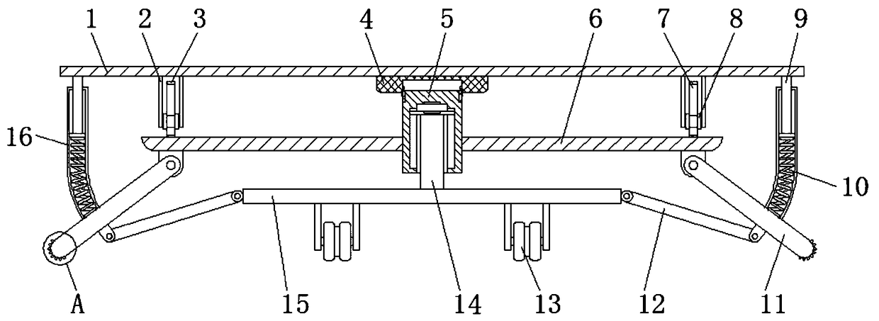
  • An unmanned aerial vehicle undercarriage with good shock absorbing effect
  • An unmanned aerial vehicle undercarriage with good shock absorbing effect
  • An unmanned aerial vehicle undercarriage with good shock absorbing effect

Examples


Embodiment Construction

[0023] The following will clearly and completely describe the technical solutions in the embodiments of the present invention with reference to the accompanying drawings in the embodiments of the present invention. Obviously, the described embodiments are only some, not all, embodiments of the present invention.

[0024] In describing the present invention, it should be understood that the terms "upper", "lower", "front", "rear", "left", "right", "top", "bottom", "inner", " The orientation or positional relationship indicated by "outside", etc. is based on the orientation or positional relationship shown in the drawings, and is only for the convenience of describing the present invention and simplifying the description, rather than indicating or implying that the referred device or element must have a specific orientation, so as to Specific orientation configurations and operations, therefore, are not to be construed as limitations on the invention.

[0025] refer to Figure ...


PUM


Abstract

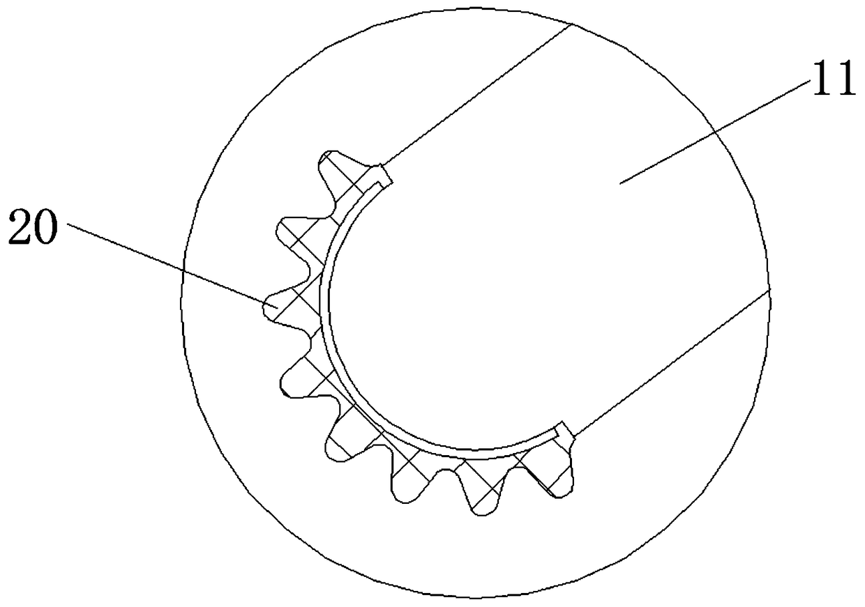
The invention discloses an unmanned aerial vehicle undercarriage with good shock absorbing effect, including a fixing plate, wherein the top outer wall of the fixing plate is provided with a fixing sleeve mounting groove, a fixing sleeve is welded on the inner wall of the fixing sleeve mounting groove, one side inner wall of the fixing sleeve is slidably connected with a sliding bar, and a connecting plate is welded on the bottom outer wall of the sliding bar, two sides of the bottom outer wall of the fixing plate are connected with supporting legs through hinges, one side outer wall of the two supporting legs and two sides outer walls of the connecting plate are connected with connecting rods through hinges, and two sides of the top outer wall of the fixing plate are welded with a limit plate. The undercarriage is helpful to ensure that the shock absorbing effect can be achieved no matter whether the unmanned aerial vehicle falls vertically or inclined. The undercarriage is helpful toimprove the protection effect of UAV and the stability of UAV. The undercarriage can further increase the frictional resistance of the supporting foot, and it is helpful to enhance the stability of the supporting foot and the stability of the supporting plate.

Description

technical field [0001] The invention relates to the technical field of unmanned aerial vehicles, in particular to an unmanned aerial vehicle landing gear with good shock absorption effect. Background technique [0002] The landing gear of the drone is a structure used to support the drone when it lands. Usually, rubber pads are set on the supporting feet of the landing gear, which can play a role in damping the vibration between the ground and the ground during take-off or landing. [0003] After searching, the Chinese Patent Publication No. is CN207875985U, which discloses a UAV landing gear with a shock-absorbing effect, including a body, a bracket is welded around the body, and a motor is installed on the top of the bracket. The top of the motor is provided with a rotating shaft on which a propeller is installed. There are still many deficiencies in the UAV landing gear disclosed in the above-mentioned patent: 1. By using the elastic force of the spring and the elasticit...

Claims


Application Information

Patent Timeline
IPC IPC(8): B64C25/62
CPCB64C25/62
Inventor 易蕾张琳杨文
Owner 易蕾
Learn More