
Rotary clamping turnover tool

A technology of turning tooling and workbench, which is applied in the field of machinery, can solve the problems of reduced work efficiency, poor consistency, and low work efficiency, and achieve the effect of improving production efficiency and production quality

Pending Publication Date: 2019-01-15
CHONGQING NO 2 MACHINE TOOL WORKS
View PDF0 Cites 4 Cited by
  • Summary
  • Abstract
  • Description
  • Claims
  • Application Information

AI Technical Summary

Problems solved by technology

[0002] At present, in the process of inspection or spraying, most of the operations still rely on manual or semi-automatic single clamping of the workpiece, resulting in low work efficiency, large errors in inspection or spraying results, poor consistency, and high labor intensity for operators.
[0003] Similarly, when the traditional gantry milling machine, gantry milling and boring machine and other large-scale equipment process the box and irregular parts, the processed product itself is rigidly clamped and cannot be rotated in multiple directions. Alignment and clamping greatly reduce work efficiency, and the product molding consistency is poor

Method used


Image

  • Rotary clamping turnover tool
  • Rotary clamping turnover tool

Examples


Embodiment Construction

[0019] Embodiments of the present invention are described in detail below, examples of which are shown in the drawings, wherein the same or similar reference numerals designate the same or similar elements or elements having the same or similar functions throughout. The embodiments described below by referring to the figures are exemplary only for explaining the present invention and should not be construed as limiting the present invention.

[0020] In the description of the present invention, unless otherwise specified and limited, it should be noted that the terms "installation", "connection" and "connection" should be understood in a broad sense, for example, it can be mechanical connection or electrical connection, or two The internal communication of each element may be directly connected or indirectly connected through an intermediary. Those skilled in the art can understand the specific meanings of the above terms according to specific situations.

[0021] The inventio...


PUM


Abstract

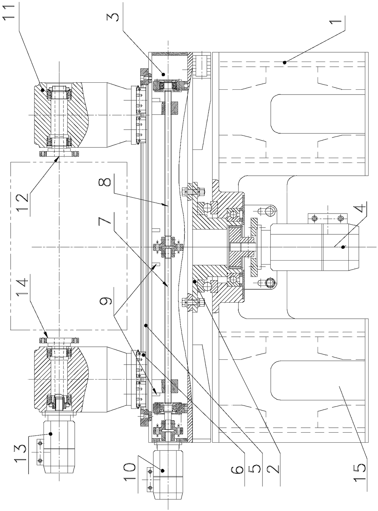
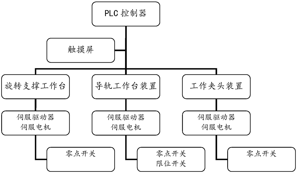
The invention provides a rotary clamping turnover tool which comprises a supporting table, a rotating fixing disc arranged on the supporting table and capable of circumferentially rotating around thecentral axis, a first servo motor which is positioned on the supporting table and can drive the rotating fixing disc to rotating around the central axis, a guide rail workbench fixed to the rotating fixing disc, a guide rail arranged on the guide rail workbench, two sliding blocks which are arranged on the guide rail and move oppositely or reversely by taking the central axis of the rotating fixing disc as the center, a screw rod mechanism driving the two sliding blocks to move in the opposite direction or the reverse direction, a second servo motor driving the screw rod mechanism to move, andtwo working clamping head bases which are correspondingly fixed on each sliding block, a first positioning part is arranged on one of the working clamping heads, and a second positioning part which is opposite to the first positioning part is arranged on the other of the working clamping heads, and a third servo motor for driving the second positioning part to rotate. According to the invention,the production efficiency and the production quality are improved.

Description

technical field [0001] The invention relates to the field of machinery, in particular to a rotary clamping turning tool. Background technique [0002] At present, in the process of inspection or spraying, most of the operations still rely on manual or semi-automatic single clamping of the workpiece, resulting in low work efficiency, large errors in inspection or spraying results, poor consistency, and high labor intensity for operators. [0003] Similarly, when the traditional gantry milling machine, gantry milling and boring machine and other large-scale equipment process the box and irregular parts, the processed product itself is rigidly clamped and cannot be rotated in multiple directions. Alignment and clamping greatly reduce work efficiency, and the product forming consistency is poor. [0004] In view of the above, it is very necessary to design a tooling for multi-directional flipping and rotating clamping of the product. Contents of the invention [0005] In ord...

Claims


Application Information

Patent Timeline
IPC IPC(8): B23Q3/06
CPCB23Q3/06
Inventor 张霄辉张孝锋刘野陈卫陈雨
Owner CHONGQING NO 2 MACHINE TOOL WORKS
Learn More