


Quick Research
Generate reliable direction feasibility study reports for your R&D in just a few steps.

Technical Q&A
Discover and master advanced knowledge NOW. Basics, ideas, possibilities, all at once.

Find Solutions
As an expert in R&D theories, this can generate solutions to your technical problems instantly.

Evaluate Feasibility
Analyze your overall solution with one click, know your potential R&D risks in advance.

Monitor Landscape
Get weekly tech updates, stay abreast of the latest tech innovations and key insights.
A test tube centrifugal vibration device for chemical experiments
A technology of chemical experiments and test tubes, applied in the field of chemical experiments, can solve the problems of not being able to hold multiple test tubes at the same time, lack of comparison of experimental results, etc.
- Summary
- Abstract
- Description
- Claims
- Application Information
AI Technical Summary
Problems solved by technology
Method used
Image


Examples
specific Embodiment approach 1
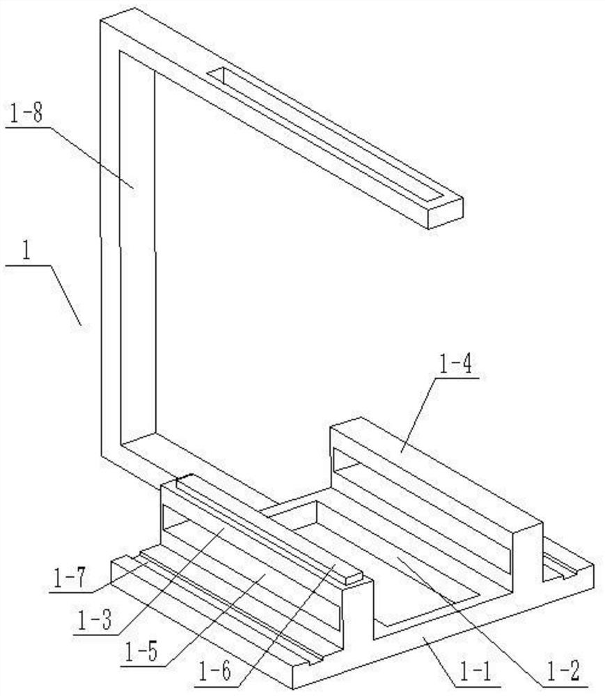
[0025] Combine below Figure 1-7 Description of this embodiment, a test tube centrifugal vibration device for chemical experiments, including a base 1, a horizontal carriage 2, a rotating frame 3, a test tube fixing seat 4 and a swing driving member 5, the base 1 includes a bottom plate 1-1, a slide Block chute 1-2, first chute seat 1-3, second chute seat 1-4, side plate chute 1-5, rack I 1-6 and C-shaped frame 1-8; bottom plate 1-1 The middle end is provided with a sliding seat chute 1-2, the first chute seat 1-3 and the second chute seat 1-4 are fixedly connected to the top surface of the bottom plate 1-1, the sliding seat chute 1-2 Located between the first chute seat 1-3 and the second chute seat 1-4, the first chute seat 1-3 and the second chute seat 1-4 are provided with side plate chute 1-5, The top surface of the first chute seat 1-3 is fixedly connected with the rack I1-6, the lower end of the C-shaped frame 1-8 is fixedly connected with the rear end of the base plat...
specific Embodiment approach 2
[0030] Combine below Figure 1-7 To illustrate this embodiment, the base 1 also includes a wheel groove 1-7; two ends of the top surface of the bottom plate 1-1 are respectively provided with a wheel groove 1-7, a first chute seat 1-3 and a second chute The seat 1-4 is located between the two wheel grooves 1-7.
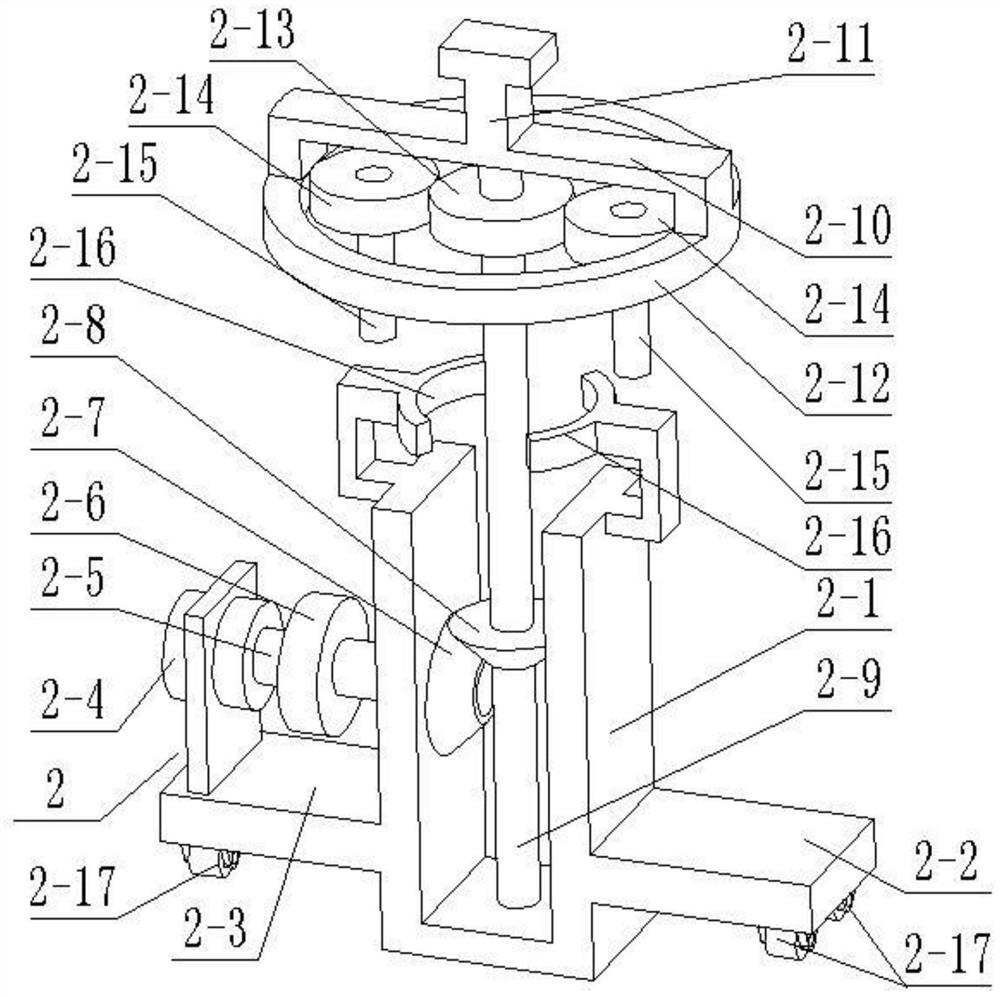
[0031] The vertical carriage 2 also includes rollers 2-17; the lower ends of the first side plate 2-2 and the second side plate 2-3 are rotatably connected with two rollers 2-17; the rollers 2-17 slide Connected in the wheel groove 1-7, the friction force during the sliding process of the first side plate 2-2 and the second side plate 2-3 is reduced.
specific Embodiment approach 3
[0033] Combine below Figure 1-7 To illustrate this embodiment, the test tube holder 4 includes a rear shaft 4-1, a rear support plate 4-2, a fixed jaw 4-3, a guide rod 4-4, a screw 4-5, and a movable jaw 4- 6, smooth rod 4-7, front support plate 4-8, front rotating shaft 4-9 and incomplete gear 4-10; The upper end of the inner end of the rotating shaft 4-1 is fixedly connected with a rear support plate 4-2, the inner end of the rear support plate 4-2 is fixedly connected with a fixed jaw 4-3, and one end of the fixed jaw 4-3 is fixedly connected with a guide rod 4 -4, the other end of the fixed jaw 4-3 is rotatably connected to the lead screw 4-5 through the bearing with seat, one end of the movable jaw 4-6 is slidably connected to the guide rod 4-4, and the movable jaw 4-6 The other end is threadedly connected to the lead screw 4-5, the movable jaw 4-6 is set opposite to the fixed jaw 4-3, and the outer end of the movable jaw 4-6 is fixedly connected to one end of the smoot...
PUM
 Abstract
Description
Claims
Application Information
 - R&D Engineer
- R&D Manager
- IP Professional
- Industry Leading Data Capabilities
- Powerful AI technology
- Patent DNA Extraction
Browse by: Latest US Patents, China's latest patents, Technical Efficacy Thesaurus, Application Domain, Technology Topic, Popular Technical Reports.
© 2024 PatSnap. All rights reserved.Legal|Privacy policy|Modern Slavery Act Transparency Statement|Sitemap|About US| Contact US: help@patsnap.com