
Overvoltage protection systems for single-phase or multi-phase power supply networks

A multi-phase power supply and overvoltage protection technology, applied in overvoltage arresters using spark gaps, circuits dedicated to spark gaps, circuits, etc., can solve problems such as spark gap aging, and achieve the effect of avoiding re-ignition and reducing wear and tear.

Active Publication Date: 2020-09-22
デーンエスエープルスツェオーカーゲー
View PDF5 Cites 0 Cited by
  • Summary
  • Abstract
  • Description
  • Claims
  • Application Information

AI Technical Summary

Problems solved by technology

Independently of the pulse current strength, all parallel-connected spark gaps ignite simultaneously, so that aging of both spark gaps also takes place

Method used


Image

  • Overvoltage protection systems for single-phase or multi-phase power supply networks
  • Overvoltage protection systems for single-phase or multi-phase power supply networks
  • Overvoltage protection systems for single-phase or multi-phase power supply networks

Examples


Embodiment Construction

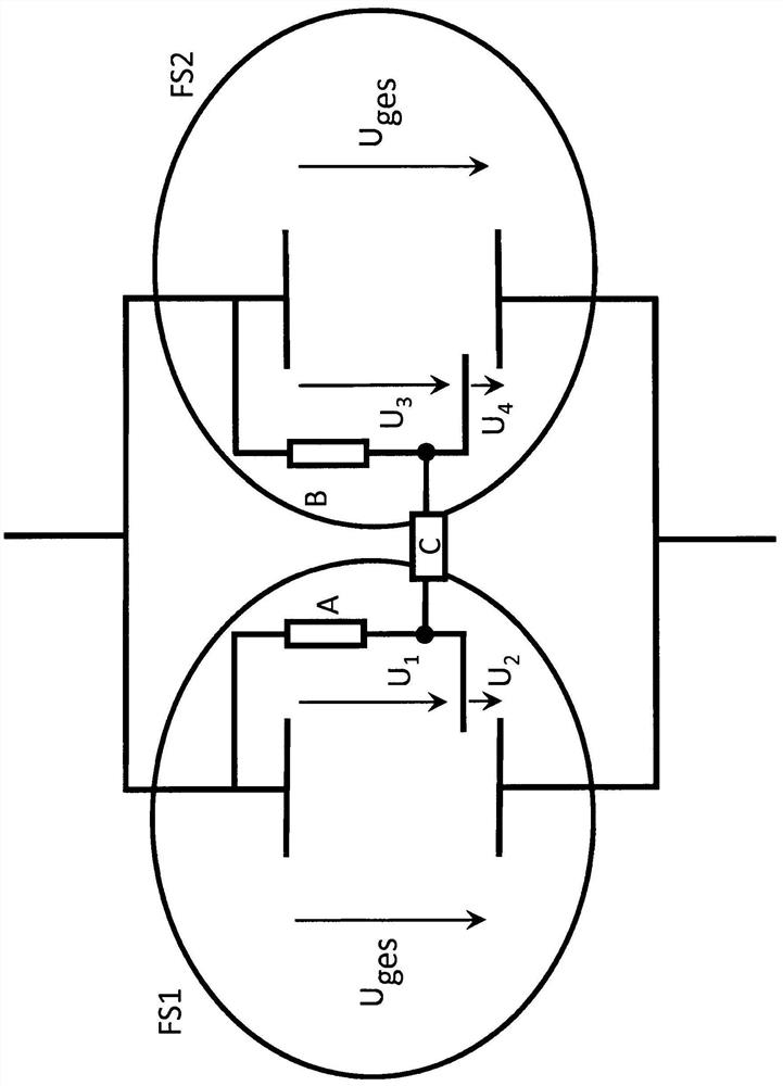
[0032] according to figure 1 , first set two parallel spark gaps FS1 and FS2.

[0033] Each spark gap has two opposite main electrodes and an ignition or trigger electrode.

[0034] Spark gap FS1 ignites when the applied overpressure exceeds a defined response value.

[0035] The response value is set by the controller A and the ignition voltage U2. In this case, an arc is formed in the spark gap FS1.

[0036] The voltage of the overall arc of the broken-down spark gap FS1 is composed of the partial voltages U1 and U2.

[0037] Only if a high voltage U2 is present at the first spark gap FS1, so that the ignition gap U4 consisting of a voltage-dependent switching element C, such as a gas arrester, and a spark gap FS2, which can be designed as a slip flash gap (Gleitstrecke) for example, is reached. The spark gap FS2 with the controller B set here is only ignited when the response value of the series configuration is reached.

[0038] Thus, by using, for example, a gas arre...


PUM


Abstract

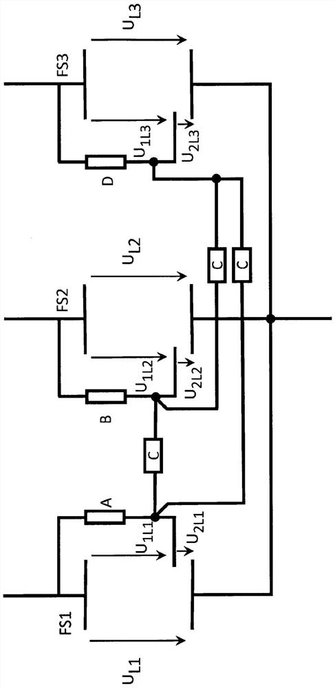
The invention relates to an overvoltage protection system for a single-phase or multi-phase power supply network, including at least two parallel-connected spark gaps, each of which is triggered. The spark gap has two main electrodes and an ignition electrode, The ignition electrode is connected to one of the main electrodes via a controller. According to the invention, in order to selectively switch on another spark gap of the parallel-connected spark gaps as required, the ignition electrodes of the respective spark gaps are connected via voltage-dependent switching elements such that the voltage-dependent switching elements are The other spark gap ignites when the response value in the series structure is formed by the ignition gap of the ignition electrode of the other spark gap.

Description

technical field [0001] The invention relates to an overvoltage protection system for a single-phase or multi-phase power supply network. Background technique [0002] From EP 1 461 852 B1 a multiphase overvoltage protection system for a multiphase supply network is known, which has at least two overvoltage protection elements. According to this solution, an overvoltage protection element is arranged in each line branch of the power supply network, each overvoltage protection element having a first and a second electrode and a spark gap acting between the two electrodes. All the above-mentioned overvoltage protection elements are arranged in a common housing. [0003] The individual overvoltage protection elements are coupled to one another in such a way that when one overvoltage protection element ignites, all other overvoltage protection elements also ignite simultaneously. In connection with this, the electrodes of the individual overvoltage protection elements are arran...

Claims


Application Information

Patent Timeline
Patent Type & Authority Patents(China)
IPC IPC(8): H01T2/02H01T4/10H01T15/00
CPCH01T2/02H01T4/10H01T15/00
Inventor U·施特朗费尔德
Owner デーンエスエープルスツェオーカーゲー
Learn More