A current-limiting type fast reclosing DC circuit breaker topology structure and control method
A DC circuit breaker and topological structure technology, applied in the direction of emergency protection circuit devices, electrical components, etc., can solve the problems of accelerating the discharge speed of inductance energy on the fault side, high cost, etc., to reduce the peak value, slow down the rising speed, and reduce the withstand current The effect of pressure
- Summary
- Abstract
- Description
- Claims
- Application Information
AI Technical Summary
Problems solved by technology
Method used
Image

Examples
Embodiment 1
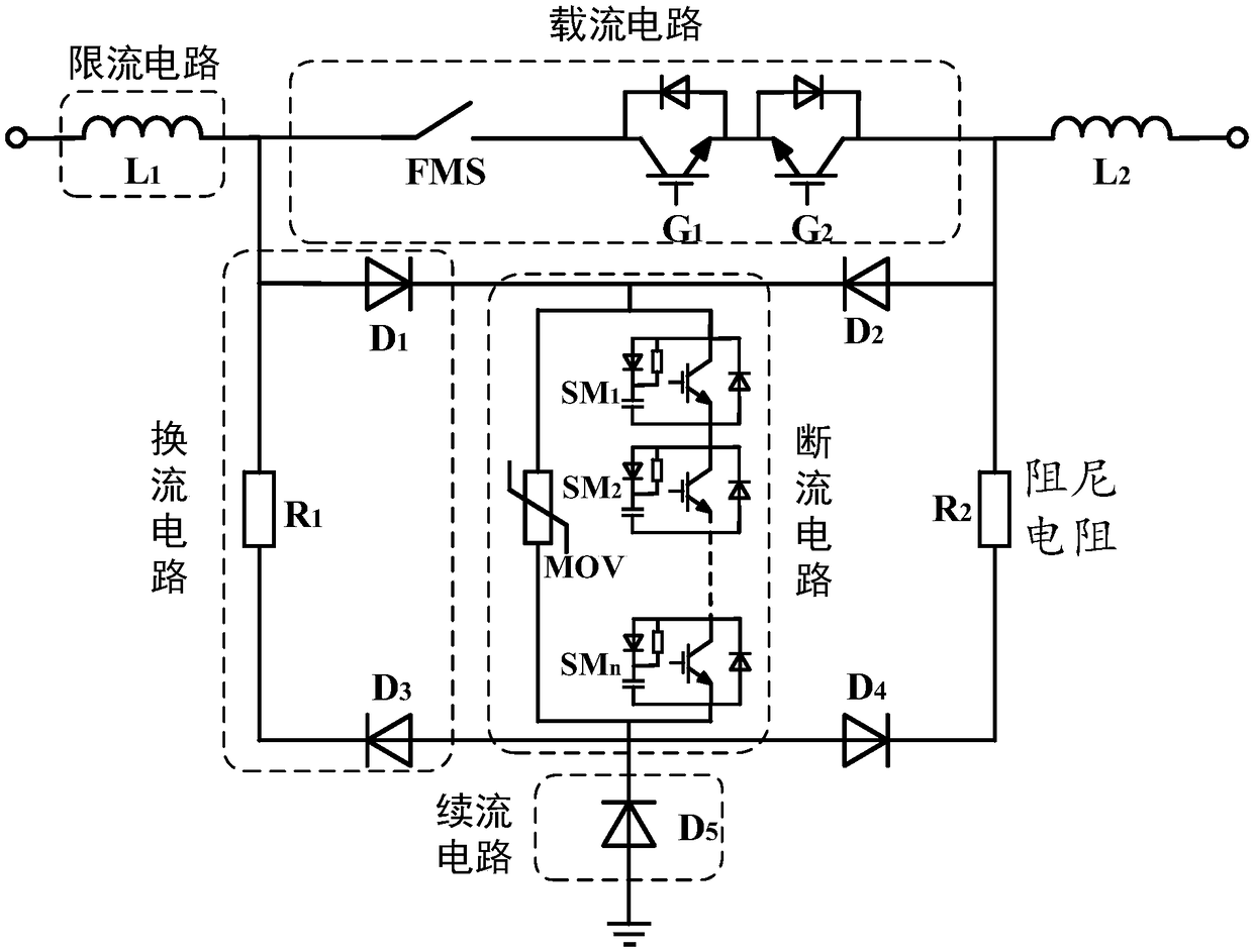
[0051] figure 1 It is a topological structure diagram of the current-limiting fast reclosing DC circuit breaker proposed by the present invention, including: including the following five parts:
[0052] ①Current-carrying circuit; composed of fast mechanical switch and auxiliary commutation switch;
[0053] ②Current limiting circuit: including two inductances of equal size, which are connected in series on both sides of the current-carrying circuit;
[0054] ③ commutation circuit; also known as diode bridge commutation circuit, which is connected in parallel with the current-carrying circuit, including four diode bridge arms and two damping resistors;
[0055] ④ Cut-off circuit; connected in series between the upper and lower bridge arms of the commutation circuit, including power electronics branch and lightning arrester branch;
[0056] ⑤ Freewheeling circuit; connected in series between the lower bridge arm of the commutation branch and the ground, also known as the freewh...
Embodiment 2
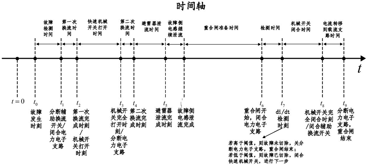
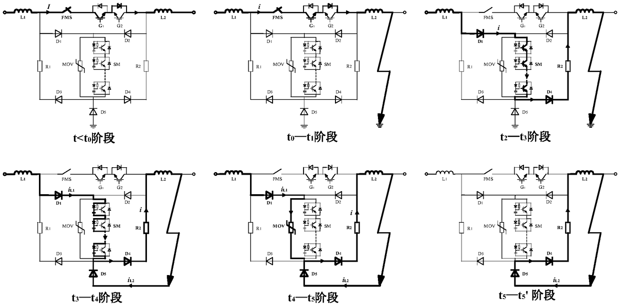
[0059] The DC circuit breaker disclosed in Embodiment 1 is placed in a single-ended DC transmission line for research, assuming that a ground fault occurs on the right side of the DC circuit breaker, then L 1 is the non-fault side inductance, L 2 is the fault side inductance. figure 2 is the specific timing diagram of the circuit breaker action, combined with figure 2 , and describe the specific action sequence of fault breaking as follows:
[0060] t=t 0 , a ground fault occurs in the circuit on the right side of the DC circuit breaker;
[0061] t=t 1 When the protection device detects that a fault occurs, the circuit breaker receives the action signal; the DC circuit breaker breaks the auxiliary commutation switch of the current-carrying circuit and closes the power electronic branch of the current-breaking branch at the same time. 1 , turn on the IGBTs in all SMs; the current is gradually commutated from the current-carrying circuit to the commutation circuit and the...
Embodiment 3
[0073] Embodiment Three: Reclosing
[0074] combine figure 2 Tell about the operation sequence of the circuit breaker proposed by the present invention when reclosing:
[0075] Suppose the fault occurs at t = t 5 When it is successfully cut off, after a short delay, it starts to reclose;
[0076] t=t 6 When , the power electronic branch is closed, that is, the IGBTs in all SMs are turned on; the current will rise again
[0077] t=t 7 , detect the electrical quantity of the fault circuit to determine whether the fault still exists; for example, detect the current rise rate di / dt, if it exceeds the preset threshold, indicating that the fault still exists, then block all IGBTs in the SM, and reclose the failure; If it is lower than the preset threshold, it means that the fault is removed, and then a conduction signal is sent to the fast mechanical switch to proceed to the next step;
[0078] t=t 8 When , the fast mechanical switch is closed, then the auxiliary commutation...
PUM
 Abstract
Description
Claims
Application Information
 - R&D
- Intellectual Property
- Life Sciences
- Materials
- Tech Scout
- Unparalleled Data Quality
- Higher Quality Content
- 60% Fewer Hallucinations
Browse by: Latest US Patents, China's latest patents, Technical Efficacy Thesaurus, Application Domain, Technology Topic, Popular Technical Reports.
© 2025 PatSnap. All rights reserved.Legal|Privacy policy|Modern Slavery Act Transparency Statement|Sitemap|About US| Contact US: help@patsnap.com