Display device

A display device and display panel technology, applied in nonlinear optics, instruments, optics, etc., to achieve the effect of reducing layout space

Inactive Publication Date: 2019-01-11
AU OPTRONICS CORP
View PDF21 Cites 1 Cited by
  • Summary
  • Abstract
  • Description
  • Claims
  • Application Information

AI Technical Summary

Problems solved by technology

The display panel is located between the cover part and the support part

Method used


Image

  • Display device
  • Display device
  • Display device

Examples


Embodiment Construction

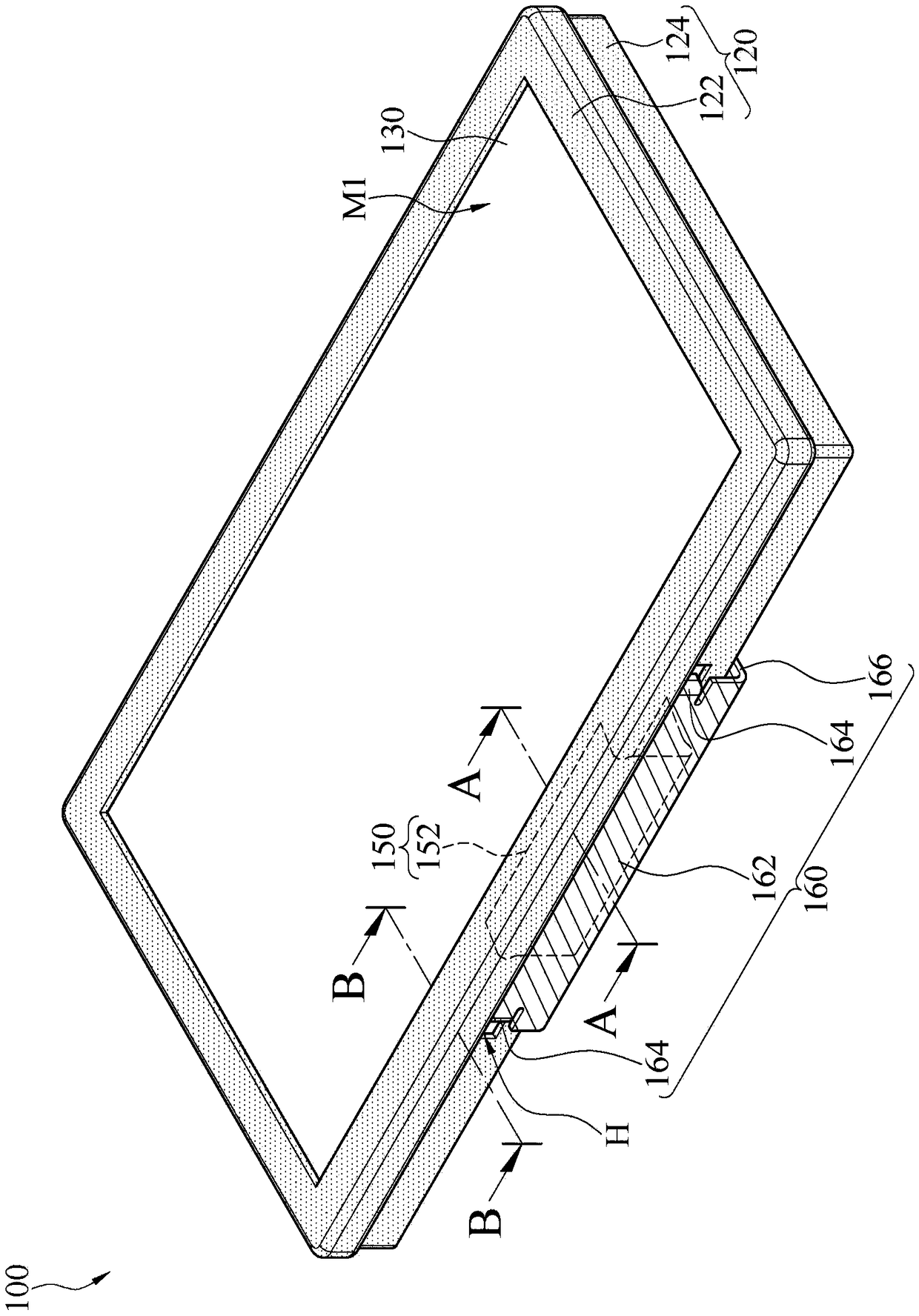
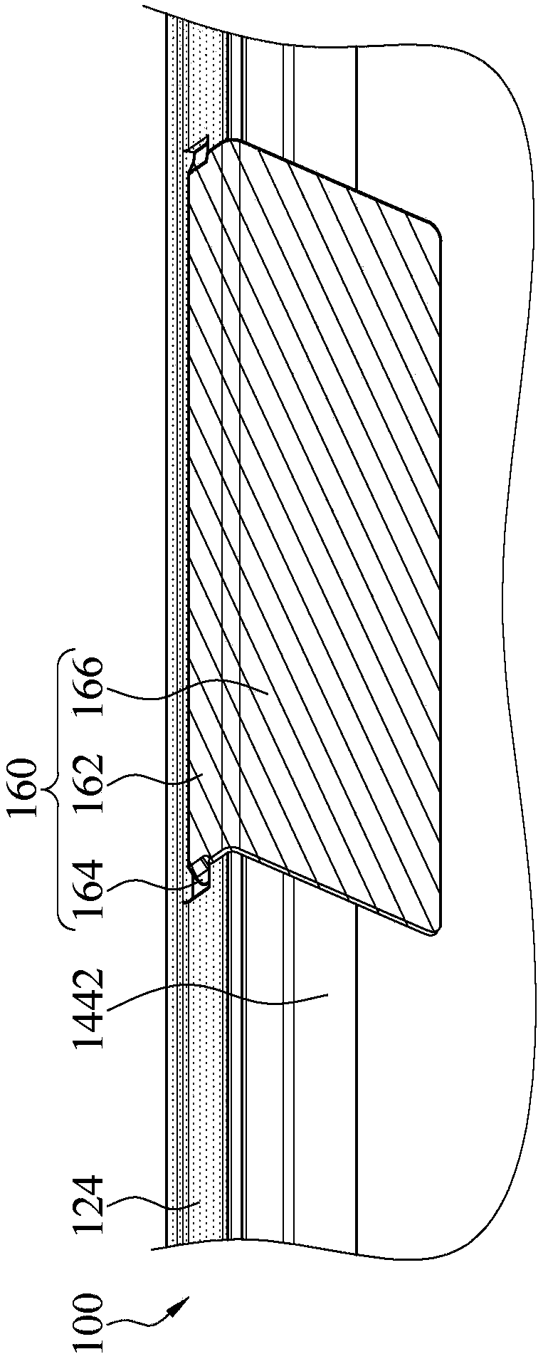
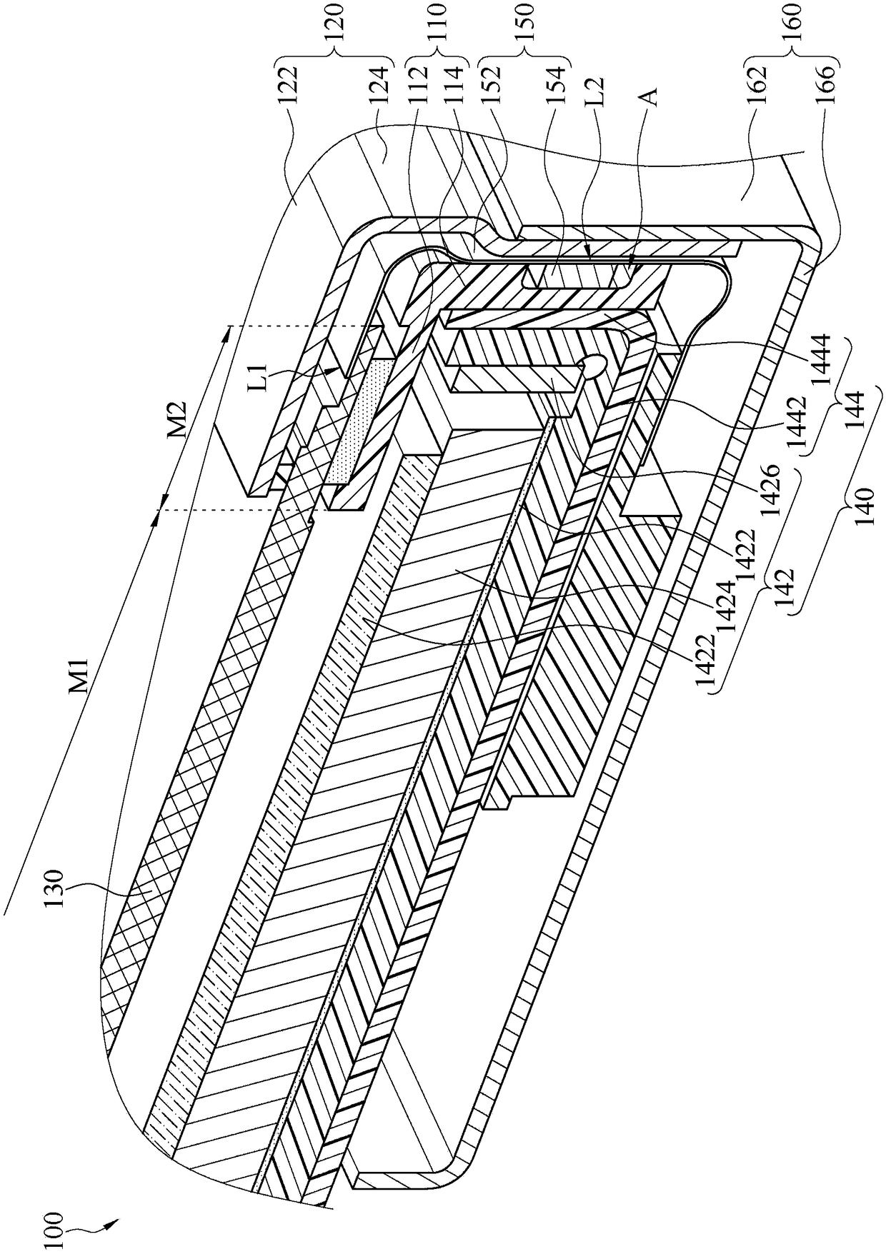
[0059] figure 1 It is a front view of a three-dimensional structure of a display device according to an embodiment of the present invention. figure 2 for correspondence figure 1 A partial bottom view of the three-dimensional structure of the display device. image 3 for corresponding to figure 1 The partial cross-sectional schematic diagram of the display device shown by the section line A-A. see figure 1 , figure 2 and image 3 The display device 100 includes a first frame body 110 , a second frame body 120 , a display panel 130 , a backlight module 140 , a circuit element 150 and at least one protective member 160 . The display panel 130 is located above the backlight module 140 , the first frame body 110 , the second frame body 120 and the protective member 160 surround the backlight module 140 , and the circuit element 150 is located between the first frame body 110 and the second frame body 120 between. in, figure 2 The section line A-A of the corresponding to...


PUM


Abstract

A display device includes a first frame, a second frame, a display panel, a backlight module, circuit components, and at least one protector. The second sidewall of the second frame is located outsidethe first sidewall of the first frame and the second sidewall has at least one slot. The display panel is located between a cover portion of the second frame and a support portion of the first frame.The backlight module is located below the support portion. The circuit components include a circuit carrier and a driver chip on the circuit carrier. The circuit carrier is located between the firstsidewall and the second sidewall and has a first edge and a second edge connected to the first edge. The protector includes a protective sidewall and a hook piece connecting the protective sidewall. The protective sidewall is located outside the second sidewall. The hook piece extends toward the second sidewall and hooks the slot of the second sidewall to be located on the second edge of the circuit carrier.

Description

technical field [0001] The invention relates to a protection technology, in particular to a display device. Background technique [0002] The design of current display devices is developing toward high resolution. In the pursuit of high resolution, more and more driver chips or other electronic components are required, and the layout of the driving circuit is becoming more and more complicated. Therefore, the protection requirements of display devices for driver chips or other electronic components are also increasing. Harsh. [0003] Generally speaking, the protection technology commonly used at present is to lock the protection shell on the side wall of the front frame or the plastic frame by using a locking member (such as a screw), and the locking member is locked to the driver chip or other electronic components. The gap between them is used to make the protective case located outside the driver chip or other electronic components. [0004] However, since the current...

Claims


Application Information

Patent Timeline
IPC IPC(8): G02F1/1333
CPCG02F1/133308G02F1/133317
Inventor 陈锦文
Owner AU OPTRONICS CORP
Why Eureka
Try Eureka