
Ox horn type electrolytic capacitor electric leakage test device, method and system

A technology of electrolytic capacitors and testing devices, which is applied in the direction of measuring devices, measuring electricity, and measuring electrical variables, etc. It can solve the problems of low accuracy of test results, waste of manpower, time cost, and cumbersome maintenance process, so as to save time, cost and manpower cost, improved reliability and accuracy, and the effect of simplifying the maintenance process

Pending Publication Date: 2019-01-11
苏州六赫机械有限公司
View PDF0 Cites 3 Cited by
  • Summary
  • Abstract
  • Description
  • Claims
  • Application Information

AI Technical Summary

Problems solved by technology

However, since the existing fixtures are integrated fixtures, during the test process, due to the fluidity of the fixtures, the uncertainty of the test point will be caused, which will directly lead to large variables in the test results.
Moreover, since the fixture is connected in one piece, once a fault such as poor contact or short circuit occurs in a certain section of the fixture, it will affect the test results of the leakage current test of the capacitor on the entire fixture
In addition, in the prior art, the leakage test of the capacitor is carried out in a non-working state, so it is impossible to test the leakage current of the capacitor in the working state.
The above defects will make it difficult to guarantee the reliability of the test results, and the accuracy of the test results is low
[0003] In addition, since the jigs in the prior art are connected in one piece, once a test failure occurs, the entire jig needs to be overhauled, and the overhaul process is cumbersome, which will cause waste of manpower, time, etc.
[0004] There are at least the following problems in the prior art: the reliability of the test results is difficult to guarantee, and the accuracy of the test results is low
It will cause waste of manpower, time, etc.

Method used


Image

  • Ox horn type electrolytic capacitor electric leakage test device, method and system
  • Ox horn type electrolytic capacitor electric leakage test device, method and system
  • Ox horn type electrolytic capacitor electric leakage test device, method and system

Examples


Embodiment Construction

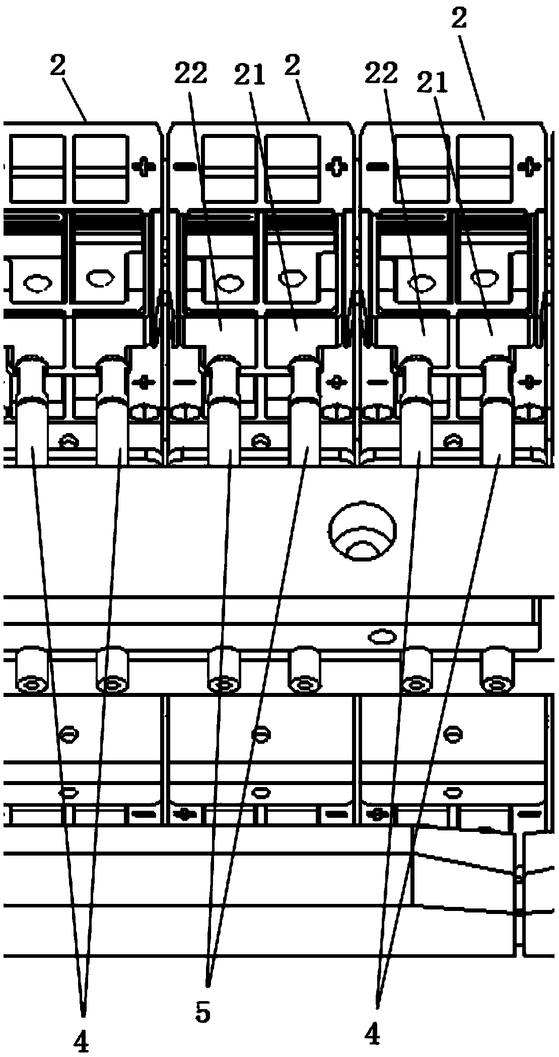
[0042] Embodiments of the present application provide a leakage test device, method and system for a horn-type electrolytic capacitor.

[0043]In order to enable those skilled in the art to better understand the technical solutions in the present application, the technical solutions in the embodiments of the present application will be clearly and completely described below in conjunction with the drawings in the embodiments of the present application. Obviously, the described The embodiments are only some of the embodiments of the present application, but not all of them. Based on the embodiments in this application, all other embodiments obtained by persons of ordinary skill in the art without creative efforts shall fall within the scope of protection of this application.

[0044] figure 1 It is a schematic diagram of the device structure of a horn-type electrolytic capacitor leakage test device provided by an embodiment of the present application. figure 2 It is a top vi...


PUM


Abstract

The invention provides an ox horn type electrolytic capacitor electric leakage test device, method and system. The device comprises a conveying mechanism and an electrode fixing plate; the conveying mechanism is fixed with capacitor fixing jigs, and each capacitor fixing jig is independent of each other and not electrically connected with each other; multiple electric leakage test electrode sets are fixed on the electrode fixing plate; each electric leakage test electrode just faces a conducting plate of the jig; at least one charging electrode set is fixed between each two electric leakage test electrode sets, and the end part of the charging electrode is in flush with the end part of the electric leakage test electrode and right faces one conducting plate of the jig; the electrode fixingplate can move forward and backward along a sliding rail along with the movement part of an air cylinder; the position right faces the electric leakage test electrode serves as an electric leakage test station, and the position right faces the charging electrode serves as a charging station. By using the device, method and system provided by each embodiment of the invention, the reliability and accuracy of the test can be improved, the overhauling process of the jig can be simplified, and time and labor costs caused by overhauling are reduced.

Description

technical field [0001] The present application relates to the technical field of electrical detection, in particular to a horn-type electrolytic capacitor leakage test device, method and system. Background technique [0002] In the field of electrical detection technology, for the leakage detection of horn-type electrolytic capacitors, the leakage current value obtained by a leakage meter test is usually used to determine whether the capacitor product is a leakage defective product. However, since the existing jigs are integrally connected jigs, during the testing process, the fluidity of the jigs will lead to the uncertainty of the test points, which will directly lead to large changes in the test results. Moreover, since the fixtures are integrally connected, once a fault such as poor contact or short circuit occurs in a certain section of the fixture, it will affect the test result of the leakage current test of the capacitor on the entire section of the fixture. In addi...

Claims


Application Information

Patent Timeline
IPC IPC(8): G01R31/02
CPCG01R31/50
Inventor 郭维国张平
Owner 苏州六赫机械有限公司
Learn More