
Vision-based method of detecting defects on end surface of bearing finished product

A defect detection and bearing technology, which is applied in the direction of optical defect/defect test, measuring device, material analysis through optical means, etc., can solve the problems of online detection of finished bearings, rust, scratches, etc., to solve online detection problems, overcome inefficient effect

Inactive Publication Date: 2019-01-11
INST OF AUTOMATION CHINESE ACAD OF SCI
View PDF6 Cites 31 Cited by
  • Summary
  • Abstract
  • Description
  • Claims
  • Application Information

AI Technical Summary

Problems solved by technology

However, the existing domestic visual inspection system cannot be applied to the online inspection of finished bearings. The main reasons are: 1) The pattern of the end face of the finished bearing is relatively complex, including chamfers, inner and outer ring end faces, sealing covers, etc.; 2) The bearing end face There are many types of defects, including rust, scratches, crushing, bumps, etc.; 3) The industrial site has high real-time requirements; 4) The accuracy of the detection of bearing end surface defects is very high, and the detection accuracy is usually required to be 0.1mm 2 Even higher, so high-resolution image sensors (above megapixels) need to be used; this puts forward higher requirements for the efficiency of visual image processing methods

Method used


Image

  • Vision-based method of detecting defects on end surface of bearing finished product
  • Vision-based method of detecting defects on end surface of bearing finished product
  • Vision-based method of detecting defects on end surface of bearing finished product

Examples


Embodiment Construction

[0047] Preferred embodiments of the present invention are described below with reference to the accompanying drawings. Those skilled in the art should understand that these embodiments are only used to explain the technical principles of the present invention, and are not intended to limit the protection scope of the present invention.

[0048] The main idea of ​​the vision-based detection method for end face defects of finished bearings of the present invention is to use machine vision light sources (RL-70-90-W) and light hoods to control the brightness of the environment, and use high-resolution industrial cameras (MV-2000UC, 200 The image collected in real time is the main information source, and the workpiece is positioned and analyzed by visual image processing, so as to realize the online automatic detection of the end surface defects of the finished bearing.

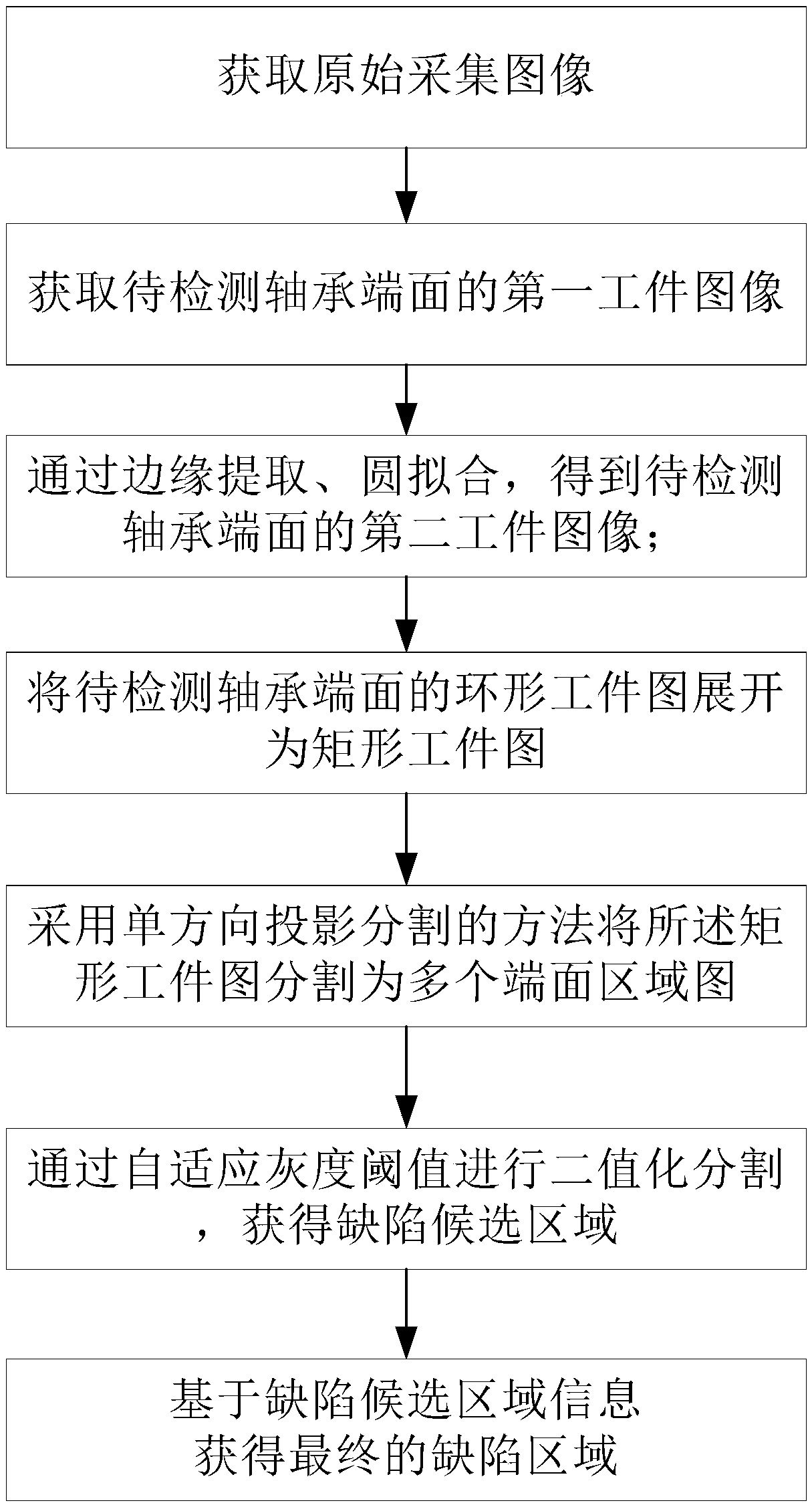
[0049] The vision-based finished bearing end surface defect detection method of the present invention comprises...


PUM


Abstract

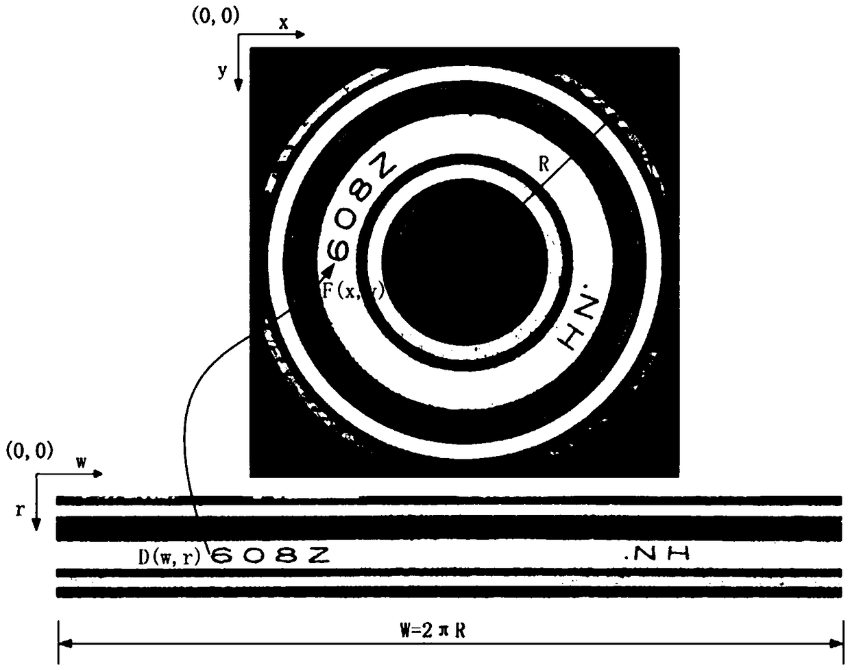
The invention belongs to the technical field of machine vision, and particularly relates to a vision-based method of detecting defects on the end surface of a bearing finished product, aiming at solving the problem of on-line detection of defects such as rust, scratches, pressed marks and bumps which probably exist on the end surface of the bearing finished product. The method comprises the following steps of: acquiring an original acquired image; acquiring a first workpiece image of the end surface of the bearing to be detected; performing edge extraction, obtaining the precise positioning ofthe bearing workpiece by using the fitting algorithm of a circle, and obtaining a second workpiece image; and based on the second workpiece image, expanding an annular workpiece drawing into a rectangular workpiece drawing; dividing the rectangular workpiece drawing into a plurality of end surface region drawings by adopting a unidirectional projection segmentation method; carrying out binarization segmentation through an adaptive gray threshold to obtain a defect candidate region; and as to the defect candidate region, obtaining a detect region by using a connected domain analysis method according to the defect position and shape information. The method realizes the on-line detection of the bearing end surface, improves the detection efficiency and the detection stability.

Description

technical field [0001] The invention belongs to the technical field of machine vision, and in particular relates to a vision-based detection method for end surface defects of finished bearings. Background technique [0002] At present, my country's bearing manufacturing industry is still dominated by traditional products, and the technical level is not high. The impact of this is that domestic bearing production is still labor-intensive, with high overall output, but low technical content, low precision, The added value of the product is low, and the quality cannot be guaranteed. Although a small number of domestic bearing manufacturers have introduced some automated and semi-automated bearing manufacturing equipment from abroad to form the production capacity of some high-precision bearing products, the quality of products cannot be guaranteed due to manual inspection and offline spot checks. , unable to meet the quality requirements of foreign users, and often face huge fi...

Claims


Application Information

Patent Timeline
IPC IPC(8): G01N21/952G01N21/88
CPCG01N21/8851G01N21/952G01N2021/8887
Inventor 李书晓朱承飞兰晓松常红星
Owner INST OF AUTOMATION CHINESE ACAD OF SCI
Learn More