
Stationary ring compensation assembly of mechanical sealing device

A mechanical seal device, static ring technology, applied in the direction of engine seal, mechanical equipment, engine components, etc., can solve the problems that the components of the static ring assembly cannot be integrated, the axial dimension is long, and the manufacturing cost is high, and the structure is simple and the shaft is high. To the effect of short size and low manufacturing cost

Inactive Publication Date: 2019-01-11
DANDONG COLOSSUS GROUP
View PDF6 Cites 0 Cited by
  • Summary
  • Abstract
  • Description
  • Claims
  • Application Information

AI Technical Summary

Problems solved by technology

[0003] The static ring compensation assembly of the above-mentioned prior art has relatively long axial dimension, complex structure, many components, and high manufacturing cost, and the various components of the static ring assembly cannot be integrated, and it is only suitable for horizontal installation and use, not for vertical installation.

Method used


Image

  • Stationary ring compensation assembly of mechanical sealing device
  • Stationary ring compensation assembly of mechanical sealing device
  • Stationary ring compensation assembly of mechanical sealing device

Examples


Embodiment Construction

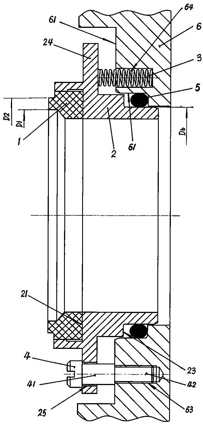
[0015] The static ring compensation assembly of the spring type mechanical seal device of the present invention is composed of a static ring 1, a static ring seat 2, a compensation spring 3, an anti-rotation screw 4, an O-shaped sealing ring 5, and a gland 6;

[0016] The front end of the static ring seat 2 is provided with an inner notch platform 21 , and the static ring 1 is installed on the inner notch platform 21 provided at the front end of the static ring seat 2 .

[0017] An outer seam 23 is provided at the rear end of the static ring seat 2, and an inner seam table 61 is provided on the central hole of the gland 6. The rear end of the static ring seat 2 is slidingly fitted with the seam of the central hole of the gland 6, O-shaped seal Ring 5 is installed on the outer seam platform 23 that static ring seat 2 rear end offers, and O type sealing ring 5 forms the sealing between static ring 1 rear end and gland 6 central holes.

[0018] An outer edge plate 24 is provided ...


PUM


Abstract

A stationary ring compensation assembly of a mechanical sealing device is composed of a stationary ring (1), a stationary ring base (2), a compensation spring (3), an anti-rotation screw (4), an O-type sealing ring (5) and a gland (6); the rear end of the stationary ring base (2) is matched with a center hole seam allowance of the gland (6) in a sliding mode, the front end portion of the stationary ring base (2) is provided with an outer edge plate (24), a cylindrical rod part (41) of the anti-rotation screw (4) is matched with an anti-rotation screw mounting hole (25) on the outer edge plate(24) of the stationary ring base in a sliding mode, the anti-rotation screw (4) is fixedly connected with the inner side end face of the gland (6), and the stationary ring base (2) and the gland (6) form axial sliding and limiting fit connection; and the compensation spring (3) is inserted into a spring mounting base hole (64) in an inner side end face (61) of the gland (6) to thrust to act on theside end face of the outer edge plate (24) of the stationary ring base (2). A stationary ring compensation element is integrated on the gland (6), transportation, mounting and use are convenient, theaxial size is short, the structure is simple, the number of composition parts is small, the manufacturing cost is low, and the stationary ring compensation assembly of the mechanical sealing device can meet the mounting use of horizontal and vertical modes.

Description

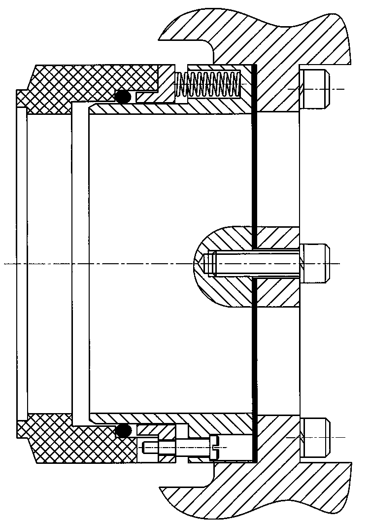
technical field [0001] The invention relates to a static ring compensating assembly of a spring type mechanical seal device. Background technique [0002] For the static ring compensation assembly of the prior art spring type mechanical seal device, see the attached figure 1 As shown, it includes static ring, static ring seat, push ring, compensation spring, anti-rotation pin, O-ring; the static ring seat fits with the gland seam and is fixed by fastening screws; At the front end of the seat, spring mounting holes are evenly distributed on the circumference of the static ring seat, and a push ring is set between the rear end of the static ring and the static ring seat. The compensation spring is installed in the spring mounting hole on the static ring seat for thrust to push the ring. The push ring acts on the static ring to perform elastic compensation for axial movement to ensure that the end face of the static ring and the end face of the moving ring are always attached....

Claims


Application Information

Patent Timeline
Patent Type & Authority Applications(China)
IPC IPC(8): F16J15/34
CPCF16J15/3436F16J15/3452
Inventor 李继明臧祖玄臧蕰棋倪宇王树伟黄继超刘晓楠董辉扈升华
Owner DANDONG COLOSSUS GROUP
Learn More