
Alarm device for wear of friction sheet

A technology of an alarm device and a friction plate, which is applied in the field of an alarm device and an alarm device for friction plate wear, can solve the problems of being unable to be used again and insufficient applicability, and achieve the effect of improving applicability

Pending Publication Date: 2019-01-11
LONGZHONG HLDG GRP
View PDF9 Cites 2 Cited by
  • Summary
  • Abstract
  • Description
  • Claims
  • Application Information

AI Technical Summary

Problems solved by technology

[0004] Although this device can avoid short-circuit phenomenon, it cannot be used again after the end of the pull rod is completely worn out. If you want to use the device again to prompt the wear of the new friction plate after replacing the new friction plate, you need to replace it with a new one. The pull rod, and other internal components connected to the pull rod and springs do not need to be replaced, but the entire device needs to be dismantled and re-fitted to make the device work normally, so the applicability is not enough

Method used


Image

  • Alarm device for wear of friction sheet
  • Alarm device for wear of friction sheet
  • Alarm device for wear of friction sheet

Examples


Embodiment 1

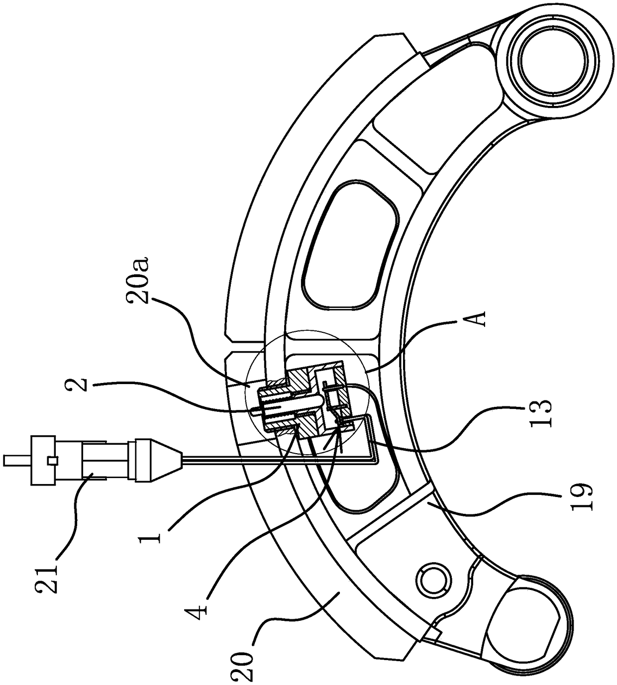
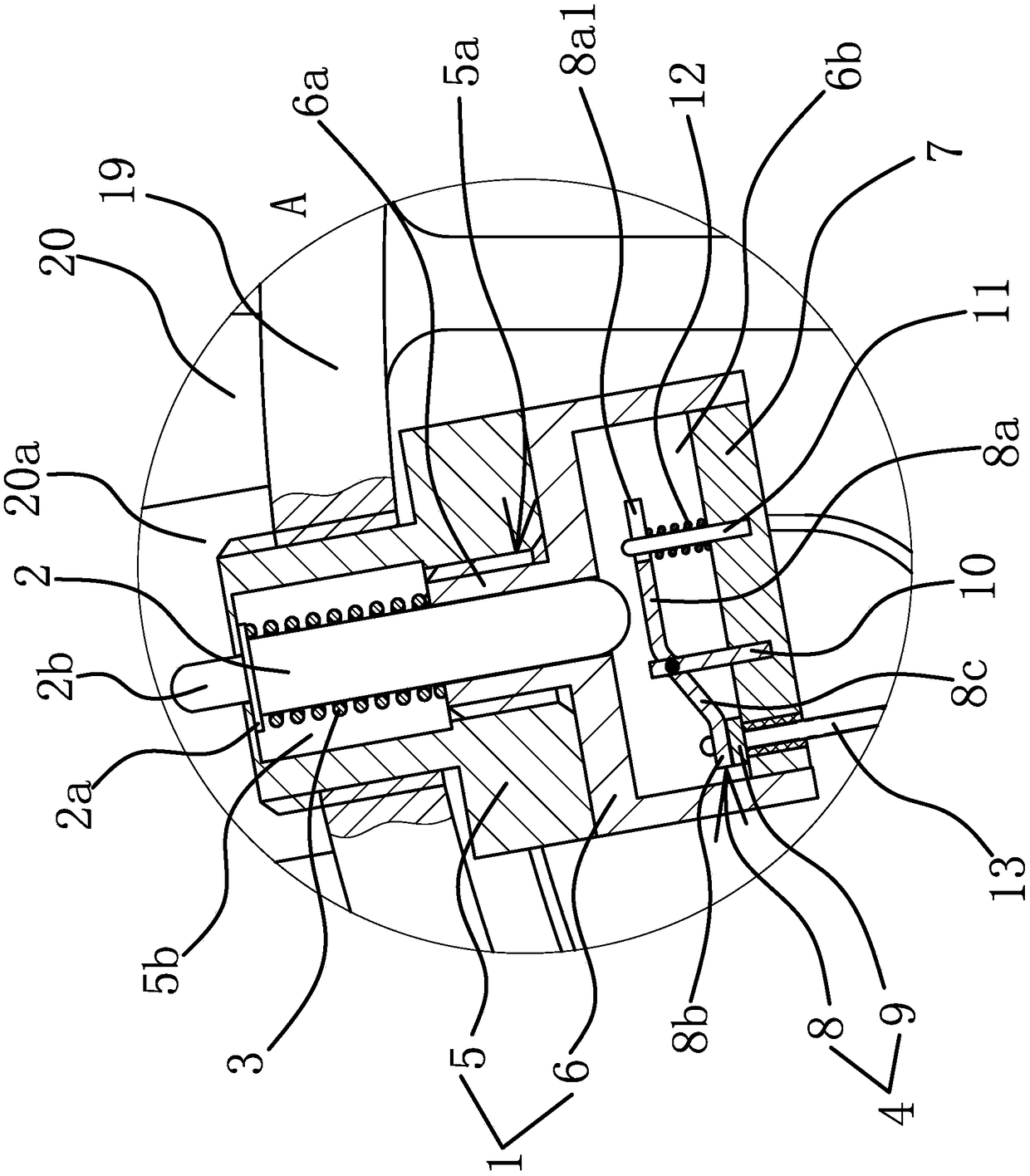
[0036] Such as figure 1 and figure 2 As shown, an alarm device for friction lining wear includes a fixed head 1 , a switch element 4 , a push rod 2 and a positioning spring 3 . The upper end of the fixed head 1 is the installation end, the push rod 2 is penetrated in the fixed head 1 and the push rod 2 can move up and down, there is a gap between the push rod 2 and the trigger element, when the push rod 2 moves down, the switch element can be triggered 4. The outside of the push rod 2 is provided with an abutment portion 2a, and the fixed head 1 is provided with an abutment surface 1a facing the lower end surface of the abutment portion 2a. On the lower end face of the resting part 2a, the lower end of the positioning spring 3 abuts against the inner wall of the fixed head 1, and the upper end face of the abutting part 2a abuts against the inner top wall of the fixed head 1 under the elastic force of the positioning spring 3, and The lower end of the push rod 2 always has ...

Embodiment 2

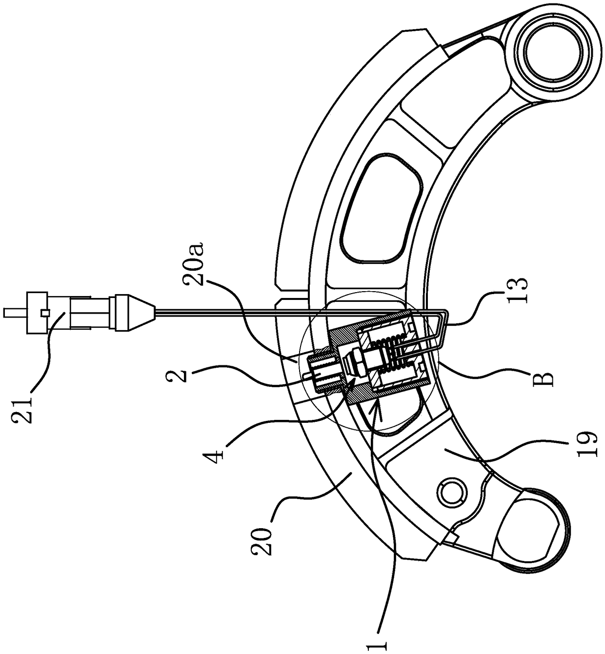
[0045] The structure and principle of this embodiment are basically the same as that of Embodiment 1, the difference is that: image 3 and Figure 4 As shown, in this embodiment, the fixing head 1 includes an upper connecting body 5 and a lower connecting body 6 , the outer upper end of the upper connecting body 5 has external threads, and the lower connecting body 6 is screwed to the lower end of the upper connecting body 5 . The lower end surface of the upper connecting body 5 is provided with a positioning cavity 5c, the lower connecting body 6 is cylindrical with an upper end open, the lower connecting body 6 is screwed in the positioning cavity 5c, and the lower end surface of the lower connecting body 6 is provided with a slot 6c.

[0046] Such as Figure 4 As shown, the switch element 4 is an inching switch, and the switch element 4 includes a cylindrical shell 14 and an inching button 15 arranged on the upper end of the shell 14. The inching button 15 is located direc...


PUM


Abstract

The invention provides an alarm device for wear of a friction sheet, belongs to the technical field of machinery, and solves the problem of low applicability of an existing alarm device. The alarm device comprises a fixed head, wherein the upper end of the fixed head is an installation end; a switch component, a push rod capable of moving up and down and triggering the switch component while moving downwards, and a location spring sleeving the push rod, are arranged in the fixed head; the upper end of the push rod stretches to the outside of the upper end of the fixed head; a gap is formed between the lower end of the push rod and the switch component; an abutting part is arranged at the outer side of the push rod; the upper end of the location spring is abutted against the lower end surface of the abutting part; the lower end of the location spring is abutted against the inner wall of the fixed head, and the upper end surface of the abutting part is abutted against the inner top wallof the fixed head under the action of the elasticity of the location spring; and the lower end of the push rod always has a trend of leaving upwards from the switch component under the action of the elasticity of the location spring. The alarm device has the advantages of being wide in applicability, simple in structure, abundant in alarm manners, and the like.

Description

technical field [0001] The invention belongs to the technical field of machinery and relates to an alarm device, in particular to an alarm device for wear of a friction plate. Background technique [0002] The most common alarm device on drum brakes on the market is composed of an alarm harness and a vehicle connector. The vehicle connector is connected to the alarm set in the cab or the vehicle computer, and the alarm harness is connected to the vehicle connector. And form a conduction alarm circuit and fix an induction head on the alarm wire harness and be installed in the friction block, so the induction head will wear with the friction block, and then when the induction head wears to the alarm wire harness is worn off, the alarm circuit is broken. The alarm or the vehicle computer will sound an alarm to improve the driver. However, such worn-out wear indicating devices are all of one-piece structure, and cannot be used after being used once, and can only be replaced as ...

Claims


Application Information

Patent Timeline
Patent Type & Authority Applications(China)
IPC IPC(8): F16D66/02
CPCF16D66/022
Inventor 胡志勇苏辉肖水波
Owner LONGZHONG HLDG GRP
Learn More