
Low-resistance electromagnetic pin puller and spacecraft

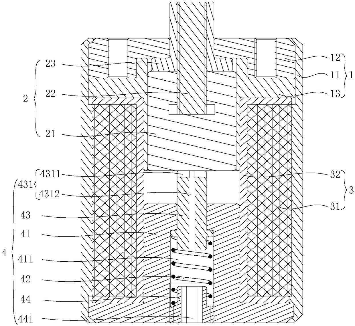
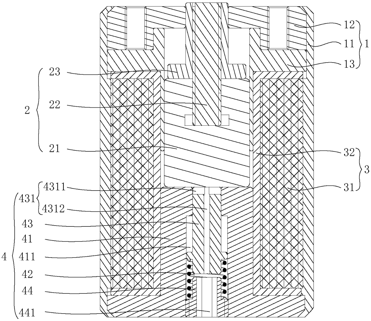
A pin-puller, low-resistance technology, applied in the aerospace field, can solve the problems of delayed pin action, inconsistent use status, and difficulty in discharging gas, and achieves the effect of reducing additional resistance and fast action.

Inactive Publication Date: 2019-01-11
天津航宇卓然科技有限公司
View PDF0 Cites 2 Cited by
  • Summary
  • Abstract
  • Description
  • Claims
  • Application Information

AI Technical Summary

Problems solved by technology

However, the internal movement space of the traditional pin puller is relatively closed. In the ground test, the gas in this space is difficult to discharge in a short time, which will generate additional resistance to the movement of the pin shaft, delay the action of the pin shaft, and have a certain impact on the ground test results. Adverse effects, making the state of the ground test inconsistent with the state of use in high altitude or space

Method used


Image

  • Low-resistance electromagnetic pin puller and spacecraft
  • Low-resistance electromagnetic pin puller and spacecraft

Examples


Embodiment Construction

[0027] The technical solutions of the present invention will be clearly and completely described below in conjunction with the accompanying drawings. Obviously, the described embodiments are part of the embodiments of the present invention, rather than all of them. Based on the embodiments of the present invention, all other embodiments obtained by those of ordinary skill in the art without creative work shall fall within the protection scope of the present invention.

[0028] In the description of the present invention, it should be noted that the terms "center", "upper", "lower", "left", "right", "vertical", "horizontal", "inner", "outer", etc. The indicated orientation or positional relationship is based on the orientation or positional relationship shown in the drawings, and is only for the convenience of describing the present invention and simplifying the description, rather than indicating or implying that the pointed device or element must have a specific orientation or a ...


PUM


Abstract

The invention provides a low-resistance electromagnetic pin puller and a spacecraft, and relates to the technical field of aerospace technologies. The low-resistance electromagnetic pin puller comprises a pin puller housing, an armature moving part, a coil assembly and a resetting mechanism, wherein the armature moving part is inserted into the pin puller housing and can move relative to the pin puller housing; the coil assembly and the reset mechanism are both arranged in the pin puller housing, and the coil assembly is arranged outside the armature moving part and the reset mechanism in a sleeving manner; and a reset gap is reserved between the reset mechanism and the armature moving part, and the reset mechanism is provided with a vent hole group for discharging air in the reset gap. The low-resistance electromagnetic pin puller can reduce the additional resistance caused by the fact that the air cannot be discharged, it is ensured that the armature moving part can move quickly, andthe use state in space is consistent with the ground test state.

Description

Technical field [0001] The invention relates to the field of aerospace technology, in particular to a low-resistance electromagnetic pin puller and a spacecraft. Background technique [0002] The electromagnetic pin puller refers to the use of the principle of electromagnetic conversion to generate electromagnetic force to attract the pin by energizing the coil assembly, and the pin moves against the resistance of the spring, thereby realizing the restriction or release of the restriction of the pin on other structures. [0003] Pin pullers are widely used in the field of aerospace and are mainly used to constrain or release key components of aircraft. Their performance directly affects the success or failure of aerospace vehicles. However, the internal movement space of the traditional pin puller is relatively closed. In the ground test, the gas in this space is difficult to be discharged in a short time, which creates additional resistance to the movement of the pin, delays the m...

Claims


Application Information

Patent Timeline
Patent Type & Authority Applications(China)
IPC IPC(8): B25B27/02
CPCB25B27/02
Inventor 魏德普吴晗玲曲展龙于兵常志龙白少刚
Owner 天津航宇卓然科技有限公司
Learn More