Projectile launching device

A launcher and projectile technology, which is applied in the military field, can solve the problems of limited manual loading speed, difficulty in large-scale popularization, high labor intensity, etc., and achieve the effects of reducing manpower, saving time, and avoiding handcuffs

Inactive Publication Date: 2019-01-08
宁波市鄞州区丰余工业产品设计有限公司
View PDF0 Cites 0 Cited by
  • Summary
  • Abstract
  • Description
  • Claims
  • Application Information

AI Technical Summary

Problems solved by technology

[0002] The mortar is a curved-fire artillery with a short body, a large firing angle, a high ballistic arc, a recoil force on the seat plate, and a finned projectile. It is fast and has a good killing effect on unprotected targets. It is suitable for shooting targets behind shelters and on reverse slopes. Since its inception, mortars have been widely used in warfare, especially in mountain warfare and trench warfare. Unit combat is a standard fire support weapon for infantry. As an effective weapon for infantry close-range fire support, it is still widely equipped by modern armies of various countries. However, in the process of operation and use, it is still basically manual operation at present. The operating skills of the shells are relatively high, and special training is required. The process of loading the shells is manual operation, which is labor-intensive, and it is easy to cause pinching of fingers. There is a certain danger. Moreover, the speed of manual loading is limited. At present, there are also some automated mortars, but the structure is too complicated, the cost is high, and it is difficult to popularize on a large scale

Method used


Image

  • Projectile launching device
  • Projectile launching device
  • Projectile launching device

Examples


Embodiment Construction

[0013] The following will clearly and completely describe the technical solutions in the embodiments of the present invention with reference to the accompanying drawings in the embodiments of the present invention. Obviously, the described embodiments are only some, not all, embodiments of the present invention. Based on the embodiments of the present invention, all other embodiments obtained by persons of ordinary skill in the art without making creative efforts belong to the protection scope of the present invention.

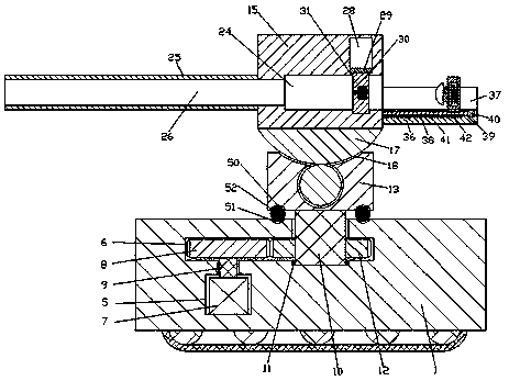
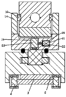
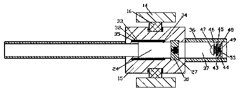
[0014] see Figure 1-3, an embodiment provided by the present invention: a projectile launching device, including a fixed base 1, a moving slot 2 with an opening downward is arranged at the middle position of the lower end surface of the fixed base 1, and the inside of the moving slot 2 is set There is a connecting block 3, and a track moving wheel 4 is symmetrically arranged on the front and rear sides of the connecting block 3, and the lower ends of the trac...


PUM


Abstract

The invention discloses a projectile launching device. The projectile launching device comprises a fixed base, wherein crawler belt moving wheels are symmetrically arranged on the front side and the back side of a connection block; a driving space is arranged in the left side of the inside of the fixed base; a rotating shaft extending upwards is arranged on the right side of the inside of a transmission space; the upper end of the rotating shaft passes through the upper end wall of the transmission space and is fixedly connected with a support block; a fixed shell is arranged between two support rods above the support block; a gun bore with a rightward opening is arranged in the fixed shell; a gun barrel is arranged on the left end wall of the gun bore; an ignition device extending leftwards is arranged in a sealed plate. In operation, an automatic projectile loading device is capable of reducing the manpower, avoiding the occurrence of the phenomenon that the hands are pinched duringmanually loading projectile and ensuring the safety of the staff; a projectile shell withdrawing block is capable of rapidly discharging used projectile shells; the time is reduced; the efficiency isimproved.

Description

technical field [0001] The invention relates to the military field, in particular to a projectile launching device. Background technique [0002] The mortar is a curved-fire artillery with a short body, a large firing angle, a high ballistic arc, a recoil force on the seat plate, and a finned projectile. It is fast and has a good killing effect on unprotected targets. It is suitable for shooting targets behind shelters and on reverse slopes. Since its inception, mortars have been widely used in warfare, especially in mountain warfare and trench warfare. Unit combat is a standard fire support weapon for infantry. As an effective weapon for infantry close-range fire support, it is still widely equipped by modern armies of various countries. However, in the process of operation and use, it is still basically manual operation at present. The operating skills of the shells are relatively high, and special training is required. The process of loading the shells is manual operatio...

Claims


Application Information

Patent Timeline
Patent Type & Authority Applications(China)
IPC IPC(8): F41F1/06
CPCF41F1/06
Inventor 杨旭
Owner 宁波市鄞州区丰余工业产品设计有限公司
Why Eureka
Try Eureka