Aircraft intelligent skin impact area localization method based on truncated inverse weighted sum

A technology of intelligent skinning and regional positioning, which is applied in aircraft component testing, aircraft health monitoring devices, elastic testing, etc., can solve problems such as difficulty in accurate positioning and positioning conflicts in the middle area, and achieve improved reliability, accuracy, The effect of reducing complexity

Active Publication Date: 2019-01-08
NANJING UNIV OF AERONAUTICS & ASTRONAUTICS
View PDF6 Cites 0 Cited by
  • Summary
  • Abstract
  • Description
  • Claims
  • Application Information

AI Technical Summary

Problems solved by technology

At the same time, this method can also effectively solve the problem of positioning conflicts in the network monitoring of multiple impact area monitoring systems and the problem of difficult positioning in the middle area

Method used


Image

  • Aircraft intelligent skin impact area localization method based on truncated inverse weighted sum
  • Aircraft intelligent skin impact area localization method based on truncated inverse weighted sum
  • Aircraft intelligent skin impact area localization method based on truncated inverse weighted sum

Examples


Embodiment 1

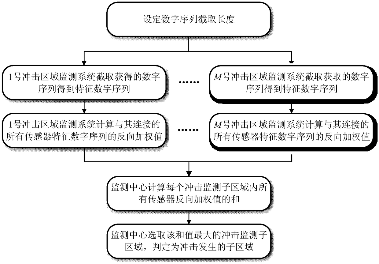
[0046] In this embodiment, P piezoelectric sensors and M impact area monitoring systems are arranged on the intelligent skin structure of the composite wing of the UAV, forming a total of Q impact monitoring sub-areas, and each impact monitoring sub-area consists of R vertices Composition, wherein P=15, M=1, Q=8, R=4. Impact is applied to No. 2 impact monitoring sub-area, the impact position is as follows image 3 shown. No. 1 to No. 15 piezoelectric sensors generate shock response signals. No. 1 shock area monitoring system converts the response signals of 15 piezoelectric sensors into digital sequences, a total of 15 digital sequences, and the length of each digital sequence obtained is K. Wherein K=500, the obtained digital sequence is as Figure 4 shown. according to Figure 5 As shown in the flow chart of the impact area positioning algorithm, the workflow of the entire monitoring system is as follows:

[0047] 1. Set a value N, and No. 1 impact area monitoring syste...

Embodiment 2

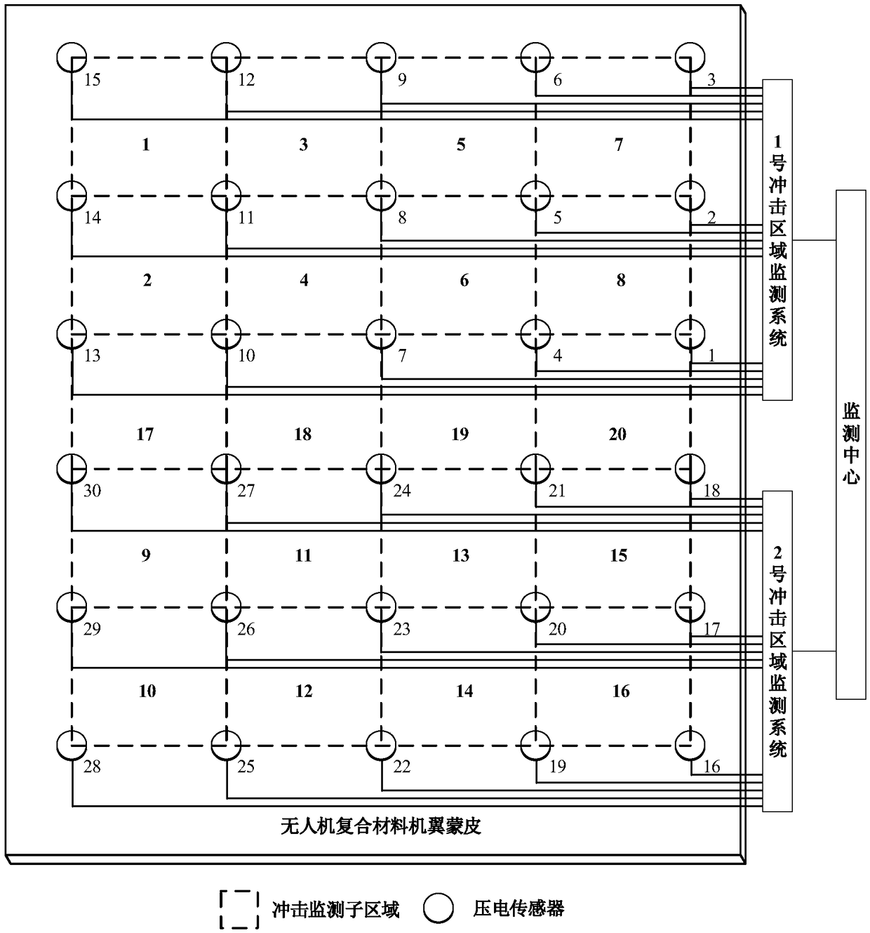
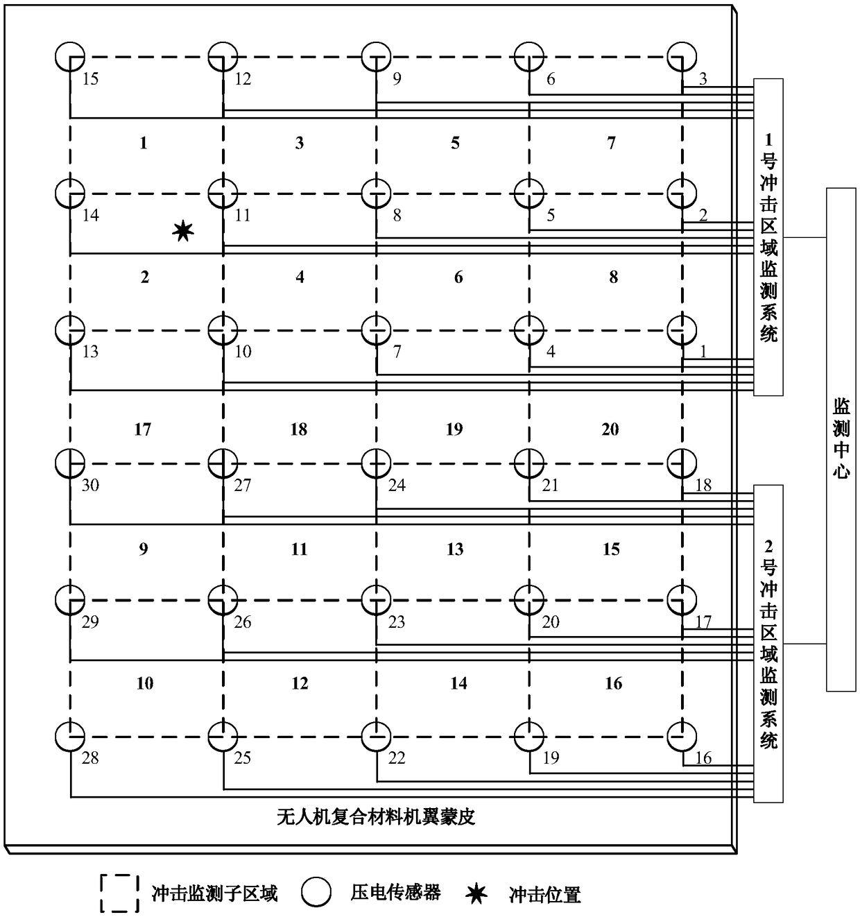
[0052] In this embodiment, P piezoelectric sensors and M impact area monitoring systems are arranged on the intelligent skin structure of the composite wing of the UAV, forming a total of Q impact monitoring sub-areas, and each impact monitoring sub-area consists of R vertices Composition, wherein P=30, M=2, Q=20, R=4. Impact is applied to the No. 17 impact monitoring sub-area, and the impact position is as follows Figure 8 shown. No. 1 to No. 30 piezoelectric sensors generate shock response signals, No. 1 impact area monitoring system converts the response signals of No. 1 to No. 15 piezoelectric sensors into digital sequences, and No. 2 impact area monitoring system converts No. The response signal of the sensor is converted into a digital sequence, a total of 30 digital sequences, the length of each digital sequence obtained is 500 points, the obtained digital sequence is as follows Figure 9 shown. according to Figure 10 As shown in the flow chart of the impact area ...


PUM


Abstract

The invention discloses an aircraft intelligent skin impact area positioning method based on truncated inverse weighted sum, belonging to the technical field of aerospace intelligent structure and health monitoring. A piezoelectric sensor array is arranged in an aircraft smart skin structure, and is connected to a plurality of impact area monitoring systems, After each impact area monitoring system obtains a digital sequence generated by the impact, At first, that numb sequence is truncated as the characteristic numb sequence, Then the monitoring center calculates the reverse weighted sum of each impact monitoring sub-region according to the piezoelectric sensors constituting the impact monitoring sub-region. Finally, the maximum impact monitoring sub-region of the reverse weighted sum isidentified as the area where the impact occurs. The invention is simple, the positioning accuracy of the impact area is high, is favorable for the embedded programming, and can solve the positioning conflict problem existing in the network monitoring of a plurality of impact area monitoring systems and the problem that the intermediate area is difficult to accurately position.

Description

technical field [0001] The invention relates to a method for locating an impact area of ​​an aircraft intelligent skin based on a truncated reverse weighted sum, and belongs to the technical field of aerospace intelligent structure and health monitoring. Background technique [0002] The basic idea of ​​aircraft intelligent skin technology is to integrate a large number of sensing / driving components and microprocessors with the skin structure to form a whole, and monitor the environment, working status and health status of the structure through a large number of sensing components. The information is processed by the microprocessor to form a control stimulus, which changes the shape, movement and force state of the structure. Intelligent skinning technology enables the skin structure itself to have the capabilities of self-diagnosis, self-adaptation, self-learning, and self-repair. Therefore, aircraft intelligent skin technology is an important technical guarantee to improv...

Claims


Application Information

Patent Timeline
Patent Type & Authority Applications(China)
IPC IPC(8): B64F5/60
CPCB64F5/60G01M5/0016G01L5/0052B64D2045/0085
Inventor 邱雷袁慎芳邓晓磊任元强
Owner NANJING UNIV OF AERONAUTICS & ASTRONAUTICS
Why Eureka
Try Eureka