Rotor, electric motor, compressor, air conditioner and method for manufacturing electric motor
A rotor and gap technology, applied in the manufacture of motor generators, electric components, air conditioning systems, etc., can solve the problems of motor efficiency decline and achieve the effect of suppressing demagnetization
- Summary
- Abstract
- Description
- Claims
- Application Information
AI Technical Summary
Problems solved by technology
Method used
Image
Examples
Embodiment approach 1
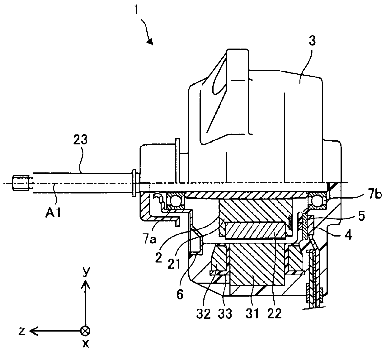
[0027] The motor 1 according to Embodiment 1 of the present invention will be described.
[0028] In the xyz rectangular coordinate system shown in each figure, the z-axis direction (z-axis) shows a direction parallel to the axis A1 (axis center) of the shaft 23 of the motor 1 (hereinafter referred to as "axis direction"), x The axial direction (x-axis) is a direction perpendicular to the z-axis direction (z-axis), and the y-axis direction is a direction perpendicular to both the z-axis direction and the x-axis direction.
[0029] figure 1 It is a cross-sectional view schematically showing the internal structure of the electric motor 1 according to Embodiment 1 of the present invention.
[0030] The motor 1 has a rotor 2, a stator 3, a substrate 4 on which electronic components such as a control circuit are mounted, a magnetic sensor 5 for detecting the rotational position of the rotor 2, a bracket 6, and bearings 7a and 7b. The motor 1 is, for example, an embedded permanen...
Deformed example 1
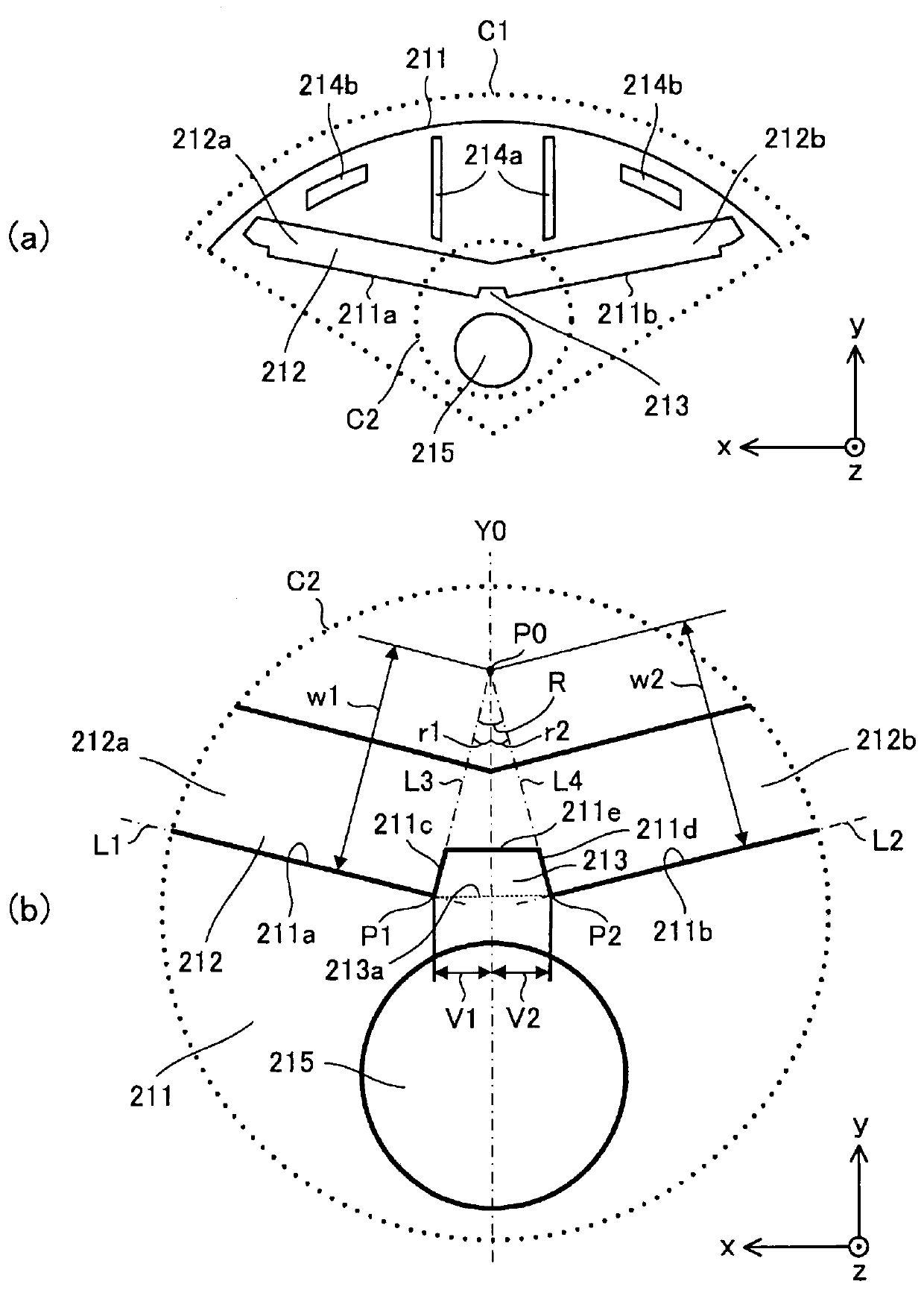
[0088] Figure 7 (a) is shown in Figure 6 (a) An enlarged view of the electromagnetic steel sheet 211 of the motor of Modification 1 of the region C4 shown by the dotted line, Figure 7 (b) is a 7b-7b sectional view of the electrical steel sheet 211 shown in (a), Figure 7 (c) is 7c-7c sectional drawing of the electrical steel sheet 211 shown in (a). With respect to the magnetic steel sheet 211 of the rotor 2 in Embodiment 1, Figure 7 z of the first end portion 211a, the second end portion 211b, the third end portion 211c, the fourth end portion 211d, and the fifth end portion 211e of the electrical steel sheet 211 in Modification 1 shown in (a) to (c). The position in the axial direction is different, and the other points are the same as those of Embodiment 1.
[0089] That is, if Figure 7 As shown in (b) and (c), the first end portion 211a, the second end portion 211b, the third end portion 211c, the fourth end portion 211d, and the fifth end portion 211e can be set ...
Deformed example 2
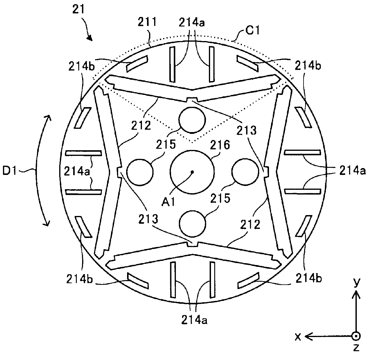
[0092] Figure 8 (a) is an enlarged view showing the structure of a part of the electromagnetic steel sheet 311 in the motor of Modification 2. FIG. Figure 8 (b) is an enlarged view showing the structure of a part of the electromagnetic steel sheet 311 of the rotor core 321 on which the permanent magnets 22 are arranged. Figure 8 (a) and (b) shown in the region C5 and figure 2 The region C1 shown corresponds to that. Compared with the rotor core 21 (specifically, the electromagnetic steel plate 211) of the rotor 2 in Embodiment 1, the structure of the magnet insertion hole 312 of the rotor core 321 (specifically, the electromagnetic steel plate 311) is different, and it is different from the rotor core 321 in other respects. Core 21 is the same. The rotor core 321 can be applied to the rotor 2 of the electric motor 1 according to Embodiment 1 instead of the rotor core 21 .
[0093] The rotor core 321 is formed by laminating a plurality of thin electromagnetic steel shee...
PUM
 Abstract
Description
Claims
Application Information
 - R&D
- Intellectual Property
- Life Sciences
- Materials
- Tech Scout
- Unparalleled Data Quality
- Higher Quality Content
- 60% Fewer Hallucinations
Browse by: Latest US Patents, China's latest patents, Technical Efficacy Thesaurus, Application Domain, Technology Topic, Popular Technical Reports.
© 2025 PatSnap. All rights reserved.Legal|Privacy policy|Modern Slavery Act Transparency Statement|Sitemap|About US| Contact US: help@patsnap.com


