
Position measurement device

A technology for measuring devices and measuring areas, which is applied in measuring devices, synchronization devices, positioning, etc., and can solve the problem of determining mobile stations by satellite positioning systems

Inactive Publication Date: 2019-01-04
ALPS ALPINE CO LTD
View PDF8 Cites 4 Cited by
  • Summary
  • Abstract
  • Description
  • Claims
  • Application Information

AI Technical Summary

Problems solved by technology

However, if the mobile station moves inside a building or in a tunnel, it is no longer possible to determine the position of the mobile station by means of a satellite positioning system

Method used


Image

  • Position measurement device
  • Position measurement device
  • Position measurement device

Examples


Embodiment Construction

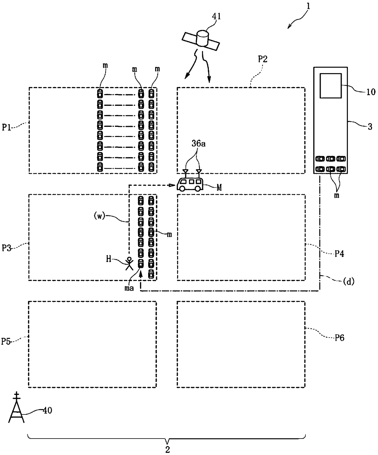
[0029] exist figure 1 The overall structure of the position measurement device 1 according to the embodiment of the present invention is shown.

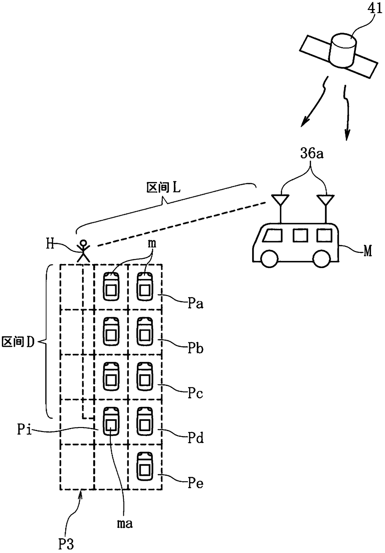
[0030] The position-determining device 1 has a measuring field 2 . The measurement area 2 is, for example, 1km 2 Waiting field for cars m above size. The measurement area 2 is divided into waiting blocks of P1, P2, P3, P4, P5, and P6. For example, a large number of cars m waiting for exit and a large number of cars m waiting for import are parked regularly arranged in each waiting block. The waiting blocks of P1, P2, P3, P4, P5, and P6 are further divided into a plurality of car spaces, and a mark indicating the position is assigned to each car parking space. exist figure 2 A part of the waiting block P3 is shown enlarged, and marks such as Pa, Pb, Pc, Pd, . . . are assigned to each parking space of the waiting block P3.

[0031] On the side of the measurement area 2, an import area 3 is provided, and the imported automobiles ...


PUM


Abstract

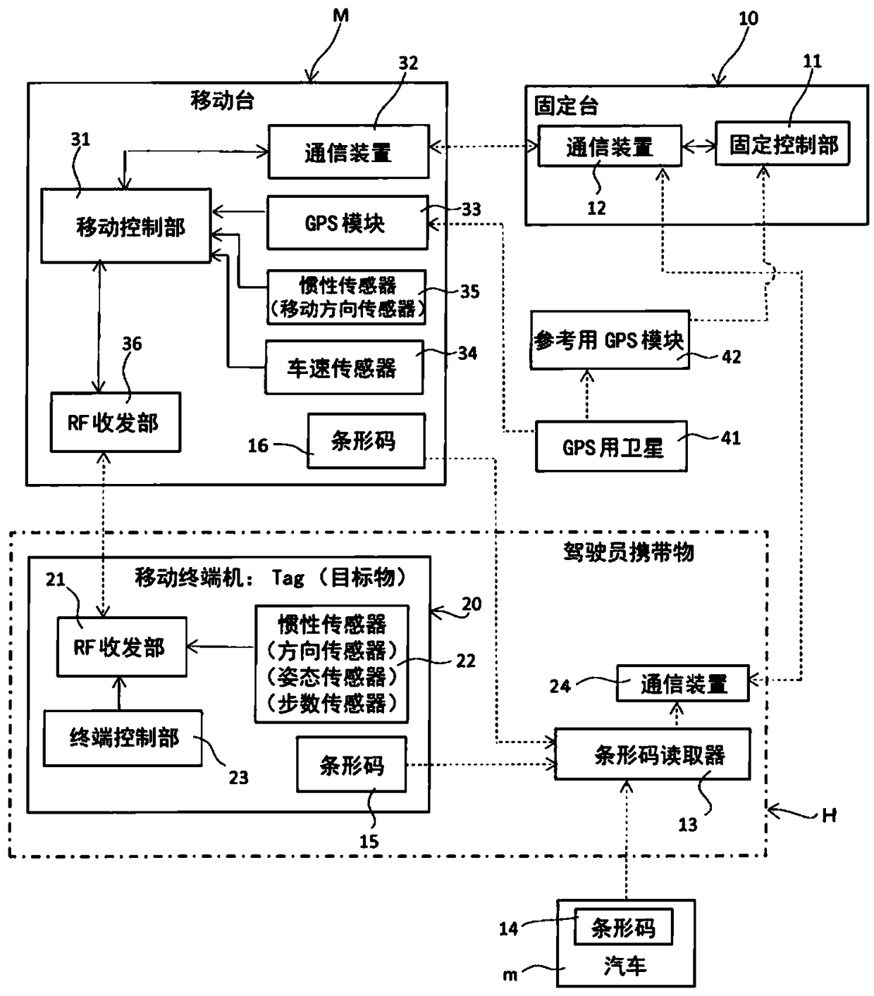
To provide a position measurement device capable of accurately detecting the position of a target within a wide measurement area. A mobile station M is moved close to a mobile terminal 20 that is a target. In ST1, the absolute position of the mobile station M within absolute coordinates (Abs) set in a measurement area is calculated. In ST2, the relative position of the mobile terminal 20 within relative coordinates (Rel) set by the mobile station M is detected. In ST3, the orientation of the mobile station M in the absolute coordinates (Abs) is detected. In ST4, the relative coordinates (Rel)are rotated. In ST5, the absolute position of the mobile terminal 20 in the absolute coordinates (Abs) is specified.

Description

technical field [0001] The present invention relates to a position measuring device capable of accurately specifying the position of an object within a relatively wide measurement area. Background technique [0002] Patent Document 1 describes an invention related to position determination in a wireless communication system. The invention determines the position of a mobile station moving within a measurement area, ie, a cellular network. [0003] In this invention, it is based on determining the position of the mobile station using a satellite positioning system such as GPS or SPS. However, if the mobile station moves inside a building or in a tunnel, it is no longer possible to determine the position of the mobile station via the satellite positioning system. In this case, communication is performed between a plurality of base stations constituting a cellular network and a mobile station, and the mobile station receives signal propagation delay information to calculate t...

Claims


Application Information

Patent Timeline
Patent Type & Authority Applications(China)
IPC IPC(8): G01S5/02G01S13/74G01S19/48G06Q10/06
CPCG01S13/74G06Q10/06G01C21/165G01S19/46G01S5/0063G01S5/14G01S13/931G01S2013/9314H04W56/0055
Inventor 若菜庆悟山田幸光高井大辅
Owner ALPS ALPINE CO LTD
Learn More