
Oil separator for separating oil from aerosols in internal combustion engines, internal combustion engines and motor vehicles

一种油分离器、内燃机的技术,应用在机器/发动机、分离方法、弥散粒子分离等方向,能够解决进气阀燃烧室结焦等问题,达到低复杂度的效果

Active Publication Date: 2021-10-08
BAYERISCHE MOTOREN WERKE AG
View PDF6 Cites 0 Cited by
  • Summary
  • Abstract
  • Description
  • Claims
  • Application Information

AI Technical Summary

Problems solved by technology

If this aerosol (blowby gas with oil) is resupplied to the combustion chamber, this can lead to coking of the intake valves, pistons and combustion chamber in long-term operation

Method used


Image

  • Oil separator for separating oil from aerosols in internal combustion engines, internal combustion engines and motor vehicles
  • Oil separator for separating oil from aerosols in internal combustion engines, internal combustion engines and motor vehicles
  • Oil separator for separating oil from aerosols in internal combustion engines, internal combustion engines and motor vehicles

Examples


Embodiment Construction

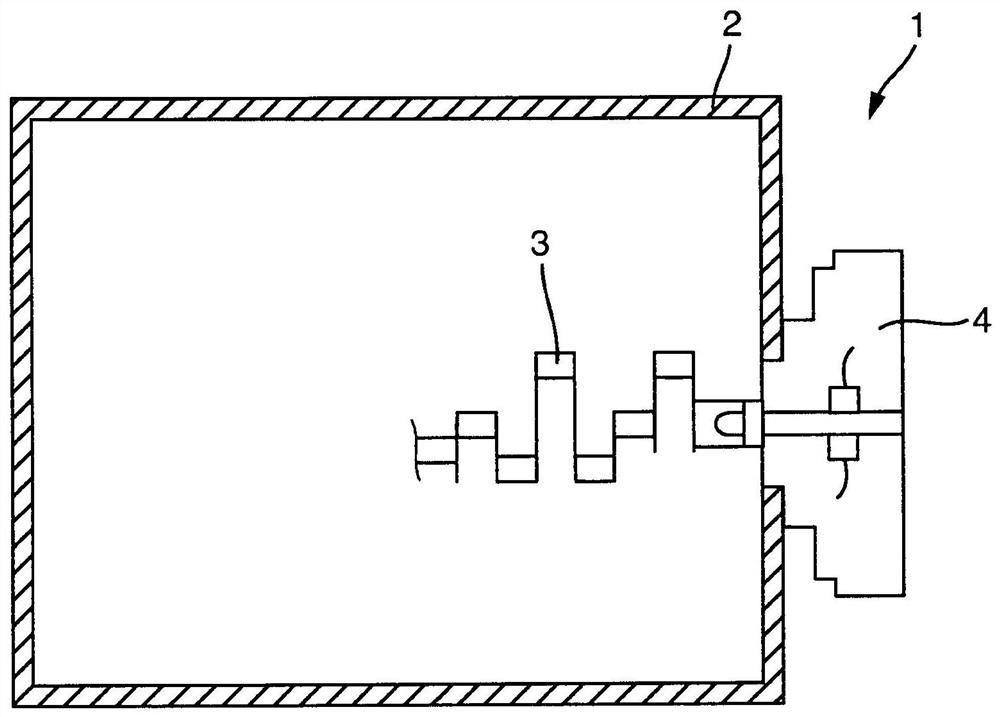
[0018] figure 1 An internal combustion engine 1 for a motor vehicle is shown schematically. Internal combustion engine 1 has a crankcase 2 and a crankshaft 3 to which an oil separator 4 according to the invention can be coupled.

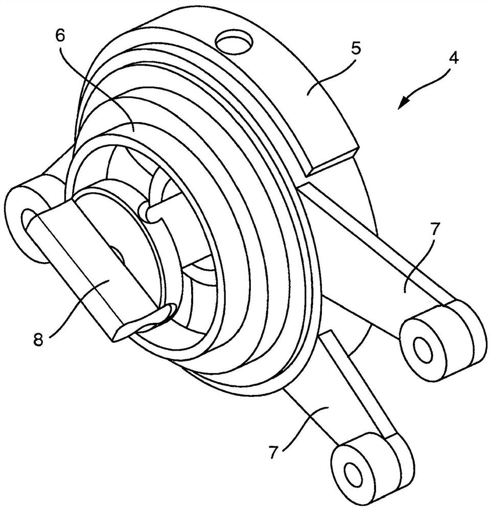
[0019] figure 2 A three-dimensional view of an oil separator 4 according to the invention is shown. The oil separator has a housing 5 with a flange neck 6 which can be inserted into the crankcase 2 and a fastening arm 7 with which the housing 5 can be fastened on the on crankcase 2. Via the engagement element 8 the oil separator 4 can be coupled to the crankshaft 3 and can be driven by it.

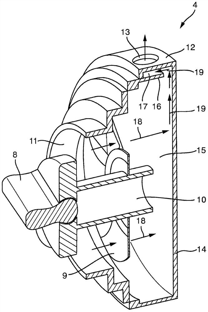
[0020] image 3 Shows figure 2 A three-dimensional cross-sectional view of the oil separator 4 in, wherein, image 3 is a sectional view along the rotation axis of the impeller 9 . Said impeller 9 is an axial impeller, ie, when rotating about its axis of rotation, the impeller 9 produces a flow parallel to its axis of rotation. The impeller 9 is mounte...


PUM


Abstract

The invention relates to an oil separator for separating oil from aerosols in an internal combustion engine, the oil separator having: a housing (5) with an inlet opening (11) for aerosols; rotatable about an axis of rotation A driven impeller (9) adapted for generating an aerosol flow in the axial direction of the impeller and arranged in the housing; and an impingement wall (15). The projection of the impeller axially and directed downstream towards the gas flow is projected onto the impingement wall and at least part of the projection of the impeller axially and directed upstream towards the gas flow is projected onto the inlet opening. The housing has air discharge openings (13) radially further outward than the impeller. A partition wall (16) is formed radially within the air outlet opening, which covers the entire surface of the air outlet opening as seen in the radial direction, by means of which a labyrinth barrier is formed in the region of the air outlet opening. The invention relates to an internal combustion engine with such an oil separator and to a motor vehicle with such an internal combustion engine.

Description

technical field [0001] The invention relates to an oil separator for separating oil from aerosols in an internal combustion engine, an internal combustion engine with such an oil separator, and a motor vehicle with such an internal combustion engine. Background technique [0002] When the internal combustion engine is running, it is unavoidable that so-called blow-by gases leak from the combustion chamber into the crankcase of the internal combustion engine through slight leaks in the piston ring gap. Said blow-by gases are usually resupplied to the subsequent combustion cycle of the internal combustion engine. After flowing through the crankcase, the oil located in the crankcase is absorbed by the blow-by gases. If this aerosol (blowby gas with oil) is resupplied to the combustion chamber, this can lead to coking of the intake valve, piston and combustion chamber during long-term operation. The oil should therefore be separated as much as possible from the aerosol before ...

Claims


Application Information

Patent Timeline
Patent Type & Authority Patents(China)
IPC IPC(8): F01M13/02F01M13/04
CPCB01D45/08F01L1/46F01L2810/02F01M13/021F01M13/04F01M2013/026F01M2013/0422F01M2013/0433
Inventor T·拉乌
Owner BAYERISCHE MOTOREN WERKE AG
Learn More