Bending Beams for Rotary Bending Machines

A technology of bending beams and bending machines, applied in the field of bending beams, can solve the problems of limited availability of bending accuracy and achieve the effects of great flexibility, reliable angle measurement, and simplified positioning

Active Publication Date: 2020-07-03
TRUMPF MASCHEN AUSTRIA
View PDF1 Cites 0 Cited by
  • Summary
  • Abstract
  • Description
  • Claims
  • Application Information

AI Technical Summary

Problems solved by technology

[0005] But existing solutions are limited to simple workpiece geometries and have limited usability for overall improved bending accuracy

Method used


Image

  • Bending Beams for Rotary Bending Machines
  • Bending Beams for Rotary Bending Machines
  • Bending Beams for Rotary Bending Machines

Examples


Embodiment Construction

[0032] First of all, it should be ensured that in the differently described embodiments, the same parts have the same reference symbols or the same component designations, wherein the disclosure contained in the entire description can reasonably be transferred to the same reference symbols or the same component designations. of the same parts. Position specifications selected in the description, such as top, bottom, side, etc., also refer to the currently described and shown figures and can be transferred to the new position in the event of a position change.

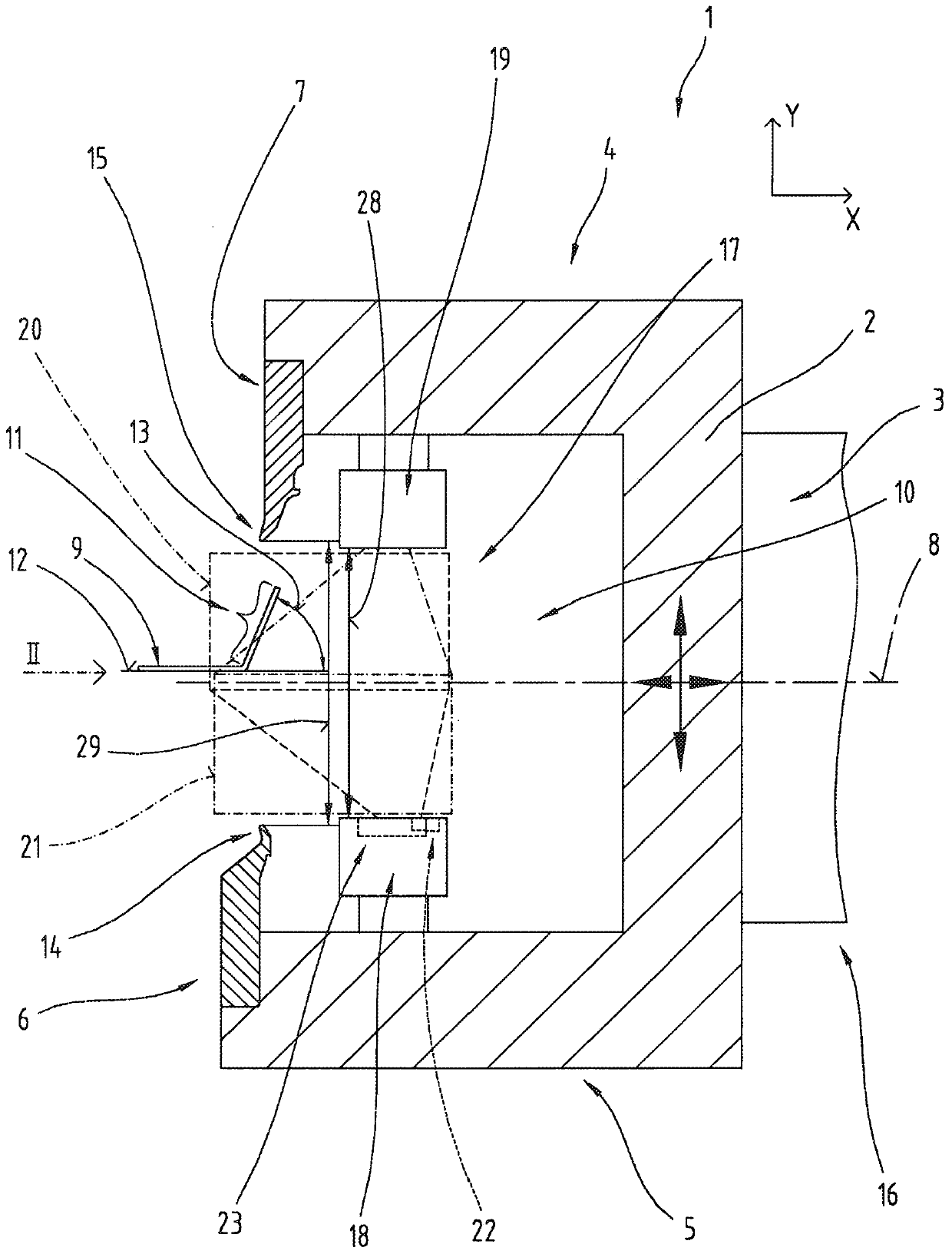
[0033] figure 1 A sectional view of a bending beam 1 of a rotary bending machine, not shown in detail, as known from the prior art is shown. The curved beam 1 is elongate perpendicular to the plane of the drawing and here has an approximately C-shaped beam cross-section 3 which essentially consists of a base 3 extending in an approximately vertical direction and two further It consists of sides 4 and 5 adjoining at th...


PUM


Abstract

The invention relates to a bending beam (1) for a rotary bending machine, said bending beam (1) being elongated with an approximately C-shaped beam cross-section (2) and two mid-planes (8) with respect to a preferably horizontal Bending tools (6, 7) extending opposite one another and facing one another in the longitudinal direction (24) of the bending beam (1), between which bending tools a workpiece section (11) to be bent of a workpiece (9) can be introduced , an angle measurement system (17) for non-contact measurement of the bending angle (13) is arranged in the interior (10) of the bending beam (1) surrounded by the C-shaped beam cross-section (2), using the The angle measuring system is capable of measuring a bending angle (13) with respect to a reference plane (12) on a workpiece section (11) bent by one of the bending tools (6, 7). Here, the angle measurement system (17) includes a first angle measurement unit (18), which is arranged below the mid-plane (8) and has a first measurement range (20), the Most of the first measurement range is located above the mid-plane (8), and the angle measurement system further includes a second angle measurement unit (19), the second angle measurement unit is arranged above the mid-plane (8) And has a second measurement range (21), most of the second measurement range is located below the mid-plane (8).

Description

technical field [0001] The invention relates to a bending beam for a rotary bending machine and to a method for measuring a bending angle on a workpiece in a rotary bending machine. [0002] The subject matter of the invention is referred to below as a bending beam, which alternatively also includes the subject matter referred to as a rotary bending machine or a beam bending machine. Background technique [0003] In order to meet the ever-increasing precision requirements for the bending angles achieved in the bent workpieces in rotary bending machines, there are already embodiments with angle measuring systems with which the forming properties of the workpieces can be detected quantitatively , especially springback, and factor it into the bending process below. A rotary bending machine is known, for example, from JP H 07275952 A1, in which a tactilely operating angle measuring system is integrated in the bending beam. [0004] Furthermore, WO 2004 / 108318 A1 discloses a ro...

Claims


Application Information

Patent Timeline
Patent Type & Authority Patents(China)
IPC IPC(8): B21D5/00B21D5/04G01B21/22
CPCB21D5/006B21D5/04G01B21/22G01B11/26G01B2210/44
Inventor M·奥金格S·施佩齐亚利
Owner TRUMPF MASCHEN AUSTRIA
Why Eureka
Try Eureka