
Unmanned aerial vehicle energy efficiency maximization resource distribution method based on physical layer safety

A physical layer security and unmanned aerial vehicle technology, which is applied in the direction of location information-based services, specific environment-based services, wireless communication, etc., to achieve good security transmission performance and low computational complexity.

Inactive Publication Date: 2019-01-04
NANCHANG UNIV
View PDF3 Cites 30 Cited by
  • Summary
  • Abstract
  • Description
  • Claims
  • Application Information

AI Technical Summary

Problems solved by technology

[0005] Although existing works have researched and designed resource allocation methods to ensure the maximum information security rate and UAV energy efficiency in the UAV ground communication system, there are only a few studies on the UAV security transmission problem and energy efficiency maximization Consider the problem at the same time, and design a resource allocation plan that considers the energy shortage limit of the UAV itself and restores the actual situation as much as possible, so as to ensure that the UAV makes full use of the resources it carries to ensure the safe and efficient transmission of the UAV ground communication

Method used


Image

  • Unmanned aerial vehicle energy efficiency maximization resource distribution method based on physical layer safety
  • Unmanned aerial vehicle energy efficiency maximization resource distribution method based on physical layer safety
  • Unmanned aerial vehicle energy efficiency maximization resource distribution method based on physical layer safety

Examples


Embodiment Construction

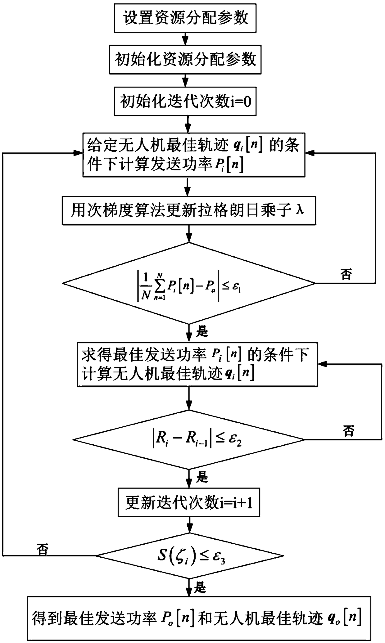
[0036] refer to figure 1 , the implementation steps of the present invention are as follows:

[0037] Step 1. Set the resource allocation parameters of the UAV communication system model.

[0038] According to the communication model between the UAV and the ground user in the actual situation, the user position coordinate is marked as q g , the eavesdropping user's location coordinates are marked as q e , The flying height of the UAV is recorded as H and its flight cycle is represented by T. The drone starts from the starting position q 0 takes off and needs to fly back to the terminal position q at the end of the flight cycle F To charge / refuel. In order to better show the flight state changes, the flight cycle is artificially divided into N segments, and the time interval of the nth segment is δ t . During the flight of the UAV, the maximum flight speed limit is recorded as V max , use P a , P max To represent. Set the convergence error ξ corresponding to the aver...


PUM


Abstract

The invention discloses an unmanned aerial vehicle energy efficiency maximization resource distribution scheme based on a physical layer safety technology, so that the purpose of maximizing the safetycapacity of the ground users is achieved. The method comprises the following steps: 1, setting parameters and initializing the parameters; 2, calculating the transmission power Pi [n] corresponding to the nth moment on the basis of the flight trajectory qi [n] of the given ith iteration; 3, updating the multiplier lambda i by using a sub-gradient iteration method according to the transmission power Pi [n]; 4, judging the average sending power constraint to obtain the sending power Pi [n] of the ith iteration; 5, utilizing the transmission power Pi [n] obtained by iteration, and calculating the parameter optimization function S (zeta i) by means of a convex optimization algorithm to obtain a flight trajectory qi [n]; 6, judging the parameter optimization function S (zeta i), judging whether the iteration stopping condition is met or not, and if the iteration stopping condition is met, the iteration stopping condition is judged, obtaining the optimal transmission power po [n] and the flight trajectory qo [n] under the optimal energy efficiency, otherwise, continuing to circulate until the condition is met. The method has the advantages of being capable of guaranteeing safe transmission of information, fast algorithm convergence, easy implementation, and can be used for wireless communication.

Description

technical field [0001] The invention belongs to the technical field of wireless communication, and relates to a resource allocation method for maximizing the energy efficiency of an unmanned aerial vehicle based on physical layer security, which can be used to maximize the safety and energy efficiency of an unmanned aerial vehicle communication system. Background technique [0002] With the rapid increase of mobile terminals and the rapid development of sensor-based smart cities, smart homes, smart grids, smart transportation, health care and other fields of the Internet of Things, ground base stations cannot meet large-scale user access during peak communication periods. The issue of entry needs to be resolved urgently. Moreover, the frequent occurrence of natural disasters in recent years has caused severe threats and damage to the ground wireless communication system. In addition, in dangerous terrain and desert areas without ground base stations, in order to monitor env...

Claims


Application Information

Patent Timeline
IPC IPC(8): H04W4/02H04W4/40H04W72/04
CPCH04W4/025H04W4/40H04W72/0473H04W72/53Y02D30/70
Inventor 钟宜洁周福辉王玉皞周辉林邓晓华周小雨秦东陈良兵洪升林洪城
Owner NANCHANG UNIV
Learn More