
A main circuit drive structure for an outdoor column switch

A transmission structure and main circuit technology, applied in electric switches, high-voltage/high-current switches, circuits, etc., can solve the problems of large conductor insulation distance, unfavorable safe and reliable operation, and large operating space, so as to achieve uniform distribution of electric field intensity, Safe and reliable long-term operation, avoiding the effect of leakage current

Pending Publication Date: 2019-01-04
XUCHANG YONGXIN ELECTRIC
View PDF7 Cites 0 Cited by
  • Summary
  • Abstract
  • Description
  • Claims
  • Application Information

AI Technical Summary

Problems solved by technology

[0002] At present, the main circuit transmission structure of outdoor pole-mounted switches basically exists in the form of bare and dispersed conductors. The insulation distance between conductors is large, and the distribution of electric field strength is scattered, which is not conducive to the miniaturization design of switches and safe and reliable operation in the power grid; The blades are all external, and the conductive parts are exposed in the environment, which is easy to cause corrosion and cause the isolation blade to fail to operate normally; the overall volume of the switch body and the isolation blade is relatively large, occupying a large operating space

Method used

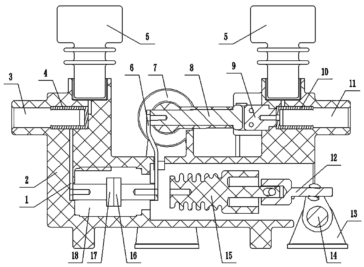
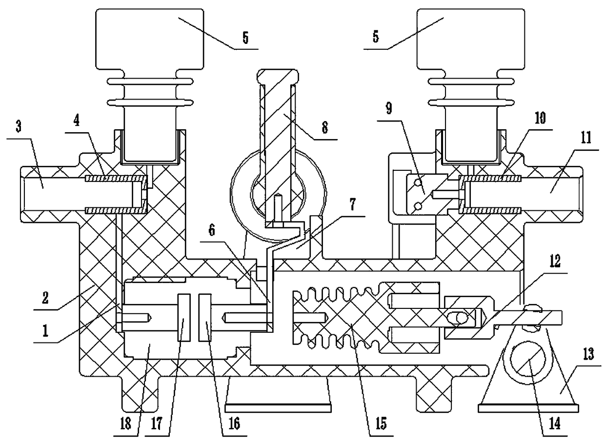

Image

  • A main circuit drive structure for an outdoor column switch
  • A main circuit drive structure for an outdoor column switch
  • A main circuit drive structure for an outdoor column switch

Examples


specific Embodiment 1

[0014] Such as figure 1 As shown, a main circuit transmission structure for an outdoor pole-mounted switch, including a solid-sealed insulation box 2, a left outlet 3 for the left side of the line is provided at the left end of the solid-sealed insulation box 2, and a use The right outlet 11 that goes out on the right side is provided with a left conductive part 4 in the left outlet 3, a right conductive part 10 is provided in the right outlet 11, and a wire is provided above the right outlet 11 and above the left outlet 3. There is a voltage sensor 5, and an isolating knife is arranged between the left outlet 3 and the right outlet 11. The isolating knife includes a knife seat, a rotary knife switch 8 and a knife switch contact 9, and the knife seat and the knife switch contact 9 are all fixed in the solid-sealed insulating box 2, the knife switch contact 9 is electrically connected with the right conductive part 10, and an arc extinguishing chamber 18 is fixed in the solid-s...

specific Embodiment 2

[0018] Such as image 3 As shown, in order to avoid the generation of leakage current, an obvious air break is required. The solid-sealed insulating box 2 includes a first insulating box 19 and a second insulating box 20. The left outlet 3 is arranged on the first insulating box 19, and the right The outlet 11 is set on the second insulating box 20, and the left conductive part 4, the arc extinguishing chamber 18, the insulating rod 15, the knife seat and the rotary knife switch 8 are covered in the first insulating box 19; the knife switch contact 9 , The right conductive member 10 is covered in the second insulating box 20 .

[0019] The main circuit transmission structure such as the isolation knife and the arc extinguishing chamber 18 is built into the solid-sealed insulating box 2, which reduces the insulation distance in the structure and uniformly distributes the electric field intensity, which is beneficial to the overall miniaturization design and avoids its overall e...


PUM


Abstract

A main circuit drive structure for an outdoor column switch is disclosed, the structure includes a sealed insulation box, a left outlet port for a left outlet line is arrange at that left end of the sealed insulation box, A right outlet for a right outlet is arrange at that right end of the sealed insulation box, A left conductive part is arranged in that left outlet port, A right conductive partis arranged in the right outlet port, an isolating knife is arranged between the left outlet port and the right outlet port, a knife switch contact is electrically connected with the right conductivepart, an arc extinguishing chamber is fixed in the sealed insulation box, the static contact of the arc extinguishing chamber is electrically connected with the left conductive part, and the moving contact of the arc extinguishing chamber is electrically connected with the rotary knife switch through a soft conductive sheet; The insulation distance in the structure is shortened and the electric field strength is uniformly distributed, which is favorable for the whole miniaturization design and avoids the whole naked leakage out of the environment, and is favorable for the safe and reliable long-term operation in the power network, by placing the isolation knife, arc extinguishing chamber and other main loop drive structures inside the sealed insulation box.

Description

technical field [0001] The invention belongs to the technical field of pole switches, in particular to a main circuit transmission structure for outdoor pole switches. Background technique [0002] At present, the main circuit transmission structure of outdoor pole-mounted switches basically exists in the form of bare and dispersed conductors. The insulation distance between conductors is large, and the distribution of electric field strength is scattered, which is not conducive to the miniaturization design of switches and safe and reliable operation in the power grid; The knives are all external, and the conductive parts are exposed in the environment, which is easy to cause corrosion and cause the isolation knives to fail to operate normally; the overall volume of the switch body and the isolation knives is relatively large, occupying a large operating space. Contents of the invention [0003] The purpose of the present invention is to provide a main circuit transmissio...

Claims


Application Information

Patent Timeline
Patent Type & Authority Applications(China)
IPC IPC(8): H01H33/42H01H21/54
CPCH01H21/54H01H33/42
Inventor 罗嗣武周晓默张会勇杨晓伦李勇超
Owner XUCHANG YONGXIN ELECTRIC
Learn More