
Intelligent lock power supply method, device and intelligent lock

A technology of smart locks and power supply status, applied in the field of smart locks, can solve problems such as inconvenience of use, and achieve the effect of enhancing security and improving experience

Inactive Publication Date: 2019-01-04
深圳市名霸科技有限公司
View PDF7 Cites 0 Cited by
  • Summary
  • Abstract
  • Description
  • Claims
  • Application Information

AI Technical Summary

Problems solved by technology

There are many types of smart locks with different functions, but there are some shortcomings of their own. The power supply is generally powered by dry batteries, but the dry batteries have a certain life. When the power is exhausted, the batteries must be replaced, so it is for the user Use brings some inconvenience

Method used


Image

  • Intelligent lock power supply method, device and intelligent lock
  • Intelligent lock power supply method, device and intelligent lock
  • Intelligent lock power supply method, device and intelligent lock

Examples


no. 1 example

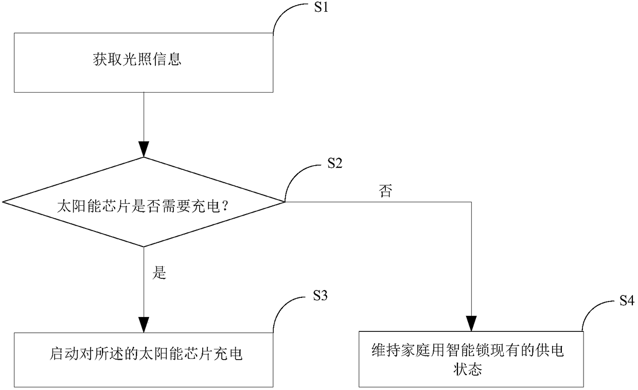
[0043] In the first embodiment of the present invention, a method for supplying power to a smart lock includes:

[0044] S1. Obtain light information;

[0045] When the light intensity reaches a certain value, it is ready to start the work of converting light energy into electrical energy.

[0046] S2. Determine whether the solar chip needs to be charged, if so, go to step S3, if not, go to step S4;

[0047] Compare with the preset value to determine whether the solar chip needs to be charged, if yes, go to step S3, if not, go to step S4.

[0048] S3. Start charging the solar chip;

[0049] Compare with the preset value to judge whether the solar chip needs to be charged, and if so, start charging the solar chip immediately.

[0050] S4. Maintain the current power supply status of the household smart lock.

[0051] Compare with the preset value to determine whether the solar chip needs to be charged. If not, maintain the current power supply status of the home smart lock p...

no. 2 example

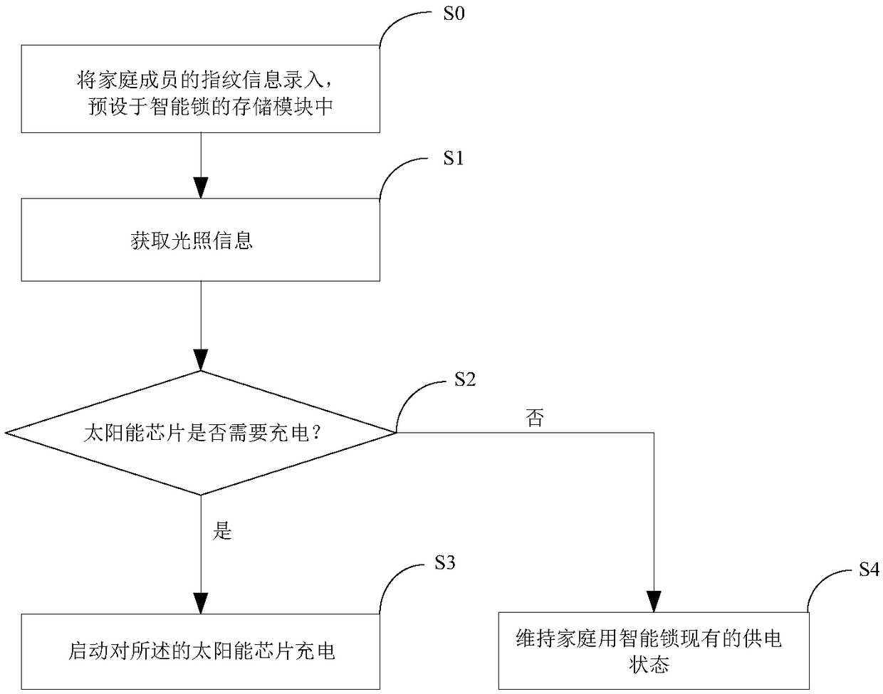
[0054] see figure 2 , the second embodiment of the present invention, a method for supplying power to a smart lock, most of the steps are the same as the first embodiment, the difference is that the following steps are also included before step S1:

[0055] S0. Enter the fingerprint information of family members and preset it in the storage module of the smart lock.

[0056] Smart locks need to pre-enter all fingerprints of persons with unlocking authority into the storage module of the smart lock for storage. Because human fingerprints are unique, no two people have the same fingerprints. Therefore, through fingerprint recognition, smart locks Security is very high.

[0057] Step S1 is specifically: acquiring illumination information through a photosensitive element.

[0058] Obtain light information through photosensitive elements, use light to convert solar energy into electric energy, and provide electric energy for smart locks, which greatly enhances the reliability an...


PUM


Abstract

The invention discloses a household intelligent lock power supply method. The method comprises the following steps: S1, obtaining illumination information; S2, judging whether a solar chip needs to becharged or not, entering a step S3 if the solar chip needs to be charged and entering a step S4 if the solar chip does not need to be charged; S3, starting charging of the solar chip; and S4, maintaining the existing power supply state of the household intelligent lock. The invention also discloses an intelligent lock power supply device and an intelligent lock. Through implementation of the intelligent lock power supply method, the intelligent lock power supply device and the intelligent lock, the solar energy is converted into electric energy so as to supply power to the household intelligent lock; the power supply is continuous and stable; the intelligent lock is energy-saving and environmentally friendly; meanwhile, the safety of the intelligent lock is also greatly improved.

Description

technical field [0001] The invention relates to an intelligent lock, in particular to a method and device for supplying power to an intelligent lock and an intelligent lock. Background technique [0002] Smart locks refer to locks that are more intelligent in terms of user identification, security, and management, which are different from traditional mechanical locks. According to the variety, there are: remote control locks, combination locks, induction card locks, etc. Among them, remote control locks mainly include optical remote control (remote control, etc.) and radio remote control (Bluetooth, etc.); coded locks currently mainly include keyboard code locks and touch keyboard code locks, which can set multiple digital passwords; induction card locks The owner uses various cards instead of keys to swipe the card to open the door. There are many types of smart locks with different functions, but there are some shortcomings of their own. The power supply is generally pow...

Claims


Application Information

Patent Timeline
IPC IPC(8): E05B49/00E05B47/00G07C9/00
CPCE05B47/00E05B49/00E05B2047/0064E05B2047/0069G07C9/00563G07C2009/0065
Inventor 敬友利敬志明王天福
Owner 深圳市名霸科技有限公司
Learn More