
Stable powder ion plasma plating equipment

An ion plasma and stable technology, which is applied in coating, melt spraying, metal material coating process, etc., can solve the problems of low production efficiency of plasma powder, inconvenient movement and use, placement and dispersion, etc., and achieves a small footprint. , easy to move and use, high production efficiency

Active Publication Date: 2019-01-04
兆基五金制品(苏州)有限公司
View PDF8 Cites 0 Cited by
  • Summary
  • Abstract
  • Description
  • Claims
  • Application Information

AI Technical Summary

Problems solved by technology

[0002] Plasma coating technology uses the plasma arc driven by direct current as the heat source to heat ceramics, alloys, metals and other materials to a molten or semi-molten state, and sprays them on the surface of the pretreated workpiece at high speed to form a firmly adhered surface layer. method, but the existing coating equipment is relatively scattered, large in size, inconvenient to move and use, and the production efficiency of plasma powder is low

Method used


Image

  • Stable powder ion plasma plating equipment
  • Stable powder ion plasma plating equipment

Examples


Embodiment 1

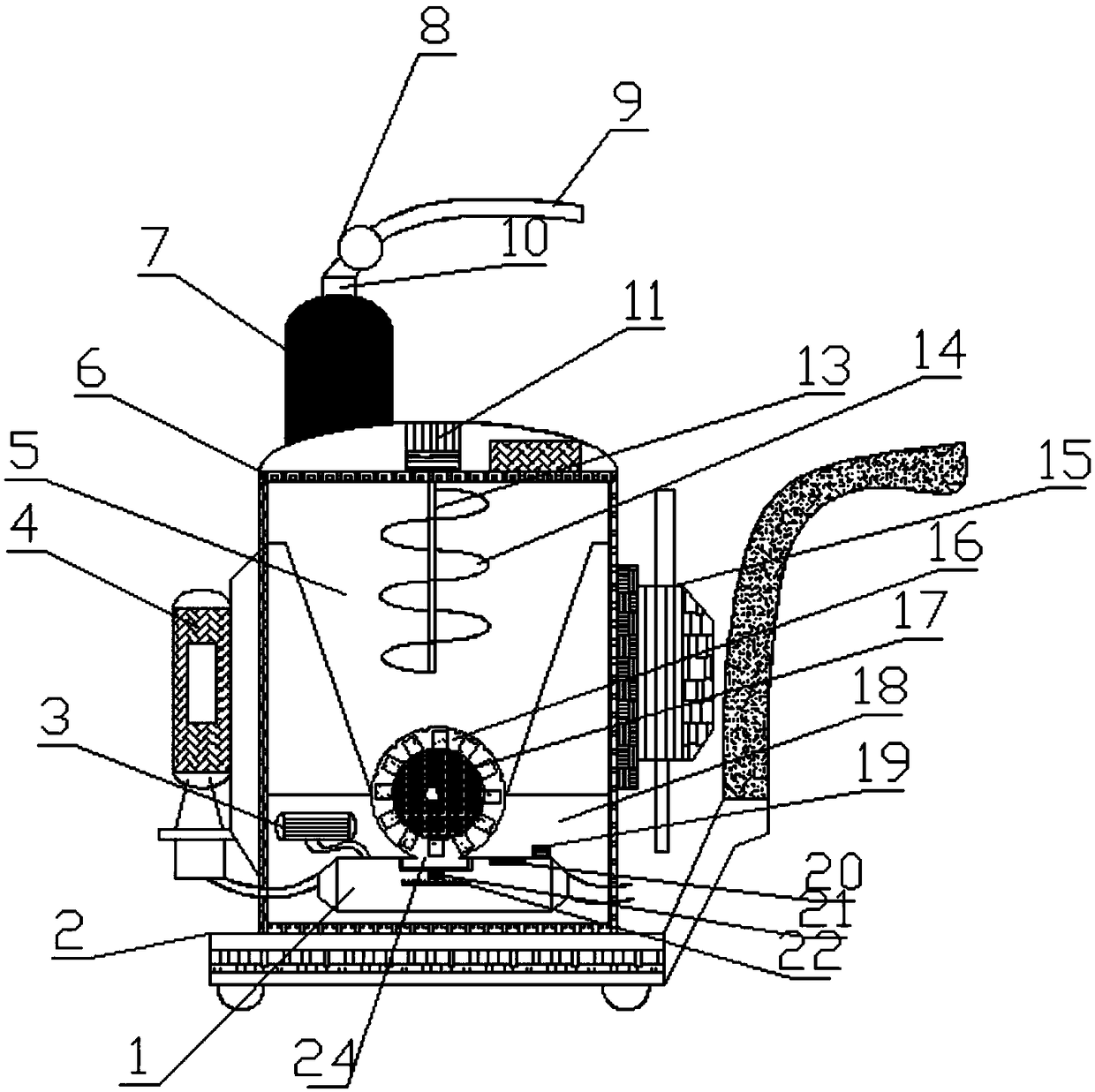
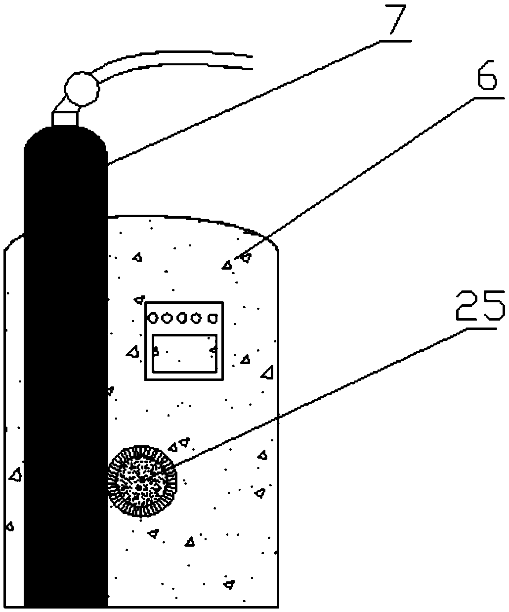
[0022] like Figure 1-2 As shown, a stable powder ion plasma coating equipment includes a base 2 and an outer shell 6, the top of the base 2 is equipped with an outer shell 6 through bolts, and one side of the outer shell 6 is provided with a hollow space through a mounting piece. Press 4, the other side of the outer casing 4 is provided with a heat exchanger 15 through a fixing member, the top of the outer casing 6 is installed with a stirring motor 11 through a mounting seat, and a stirring chamber 5 is arranged inside the outer casing 6 , the stirring chamber 5 is provided with a stirring rod 13, and the stirring rod 13 is provided with a spiral stirring blade 14 through a bolt, the bottom of the stirring chamber 5 is provided with a feeding channel 16, and the feeding channel 16 is provided with a lower Material turntable 17, the bottom of described feeding channel 16 is provided with feeding opening 24, and the lower end of described mixing chamber 5 is provided with inst...

Embodiment 2

[0036] like Figure 1-2 As shown, a stable powder ion plasma coating equipment includes a base 2 and an outer shell 6, the top of the base 2 is equipped with an outer shell 6 through bolts, and one side of the outer shell 6 is provided with a hollow space through a mounting piece. Press 4, the other side of the outer casing 4 is provided with a heat exchanger 15 through a fixing member, the top of the outer casing 6 is installed with a stirring motor 11 through a mounting seat, and a stirring chamber 5 is arranged inside the outer casing 6 , the stirring chamber 5 is provided with a stirring rod 13, and the stirring rod 13 is provided with a spiral stirring blade 14 through a bolt, the bottom of the stirring chamber 5 is provided with a feeding channel 16, and the feeding channel 16 is provided with a lower Material turntable 17, the bottom of described feeding channel 16 is provided with feeding opening 24, and the lower end of described mixing chamber 5 is provided with inst...


PUM


Abstract

The invention discloses stable powder ion plasma plating equipment. The equipment comprises a base and an outer casing, the top of the base is provided with the outer casing by a bolt, one side of theouter casing is provided with an air compressor through a mounting member, the other side of the outer casing is provided with a heat exchanger through a fixing member, the top of the outer casing isprovided with a stirring motor through a mounting seat, the outer casing is internally provided with a stirring chamber, the stirring chamber is internally provided with a stirring rod, a screw stirring blade is arranged on the stirring rod by the bolt, a blanking passage is arranged at the bottom of the stirring chamber, a blanking turntable is arranged in the blanking passage, a blanking mouthis formed in the bottom of the blanking passage, and the lower end of the stirring chamber is provided with a mounting chamber. The stable powder ion plasma plating equipment has complete functions, small floor space, simple operation and convenient production, effectively improves the efficiency of powder ion plating, and is suitable for widespread popularization and use.

Description

technical field [0001] The invention relates to the technical field of plasma plating, in particular to a stable powder ion plasma plating equipment. Background technique [0002] Plasma coating technology uses the plasma arc driven by direct current as the heat source to heat ceramics, alloys, metals and other materials to a molten or semi-molten state, and sprays them on the surface of the pretreated workpiece at high speed to form a firmly adhered surface layer. method, but the existing coating equipment is relatively scattered and has a large volume, which is inconvenient to move and use, and the production efficiency of plasma powder is low. To this end, we propose a stable powder ion plasma coating equipment. Contents of the invention [0003] The main purpose of the present invention is to provide a stable powder ion plasma coating equipment, which evenly transports the powder from the feeding port to the plasma chamber, and drives the atomization disc to rotate th...

Claims


Application Information

Patent Timeline
Patent Type & Authority Applications(China)
IPC IPC(8): C23C4/134
CPCC23C4/134
Inventor 秦小梅
Owner 兆基五金制品(苏州)有限公司
Learn More