
A kind of automobile multifunctional driving axle

A multi-functional, drive axle technology, applied in the direction of brakes, vehicle parts, brake components, etc., can solve the problems of unable to perform normal deceleration and braking, unable to brake, and unable to perform normal braking of the car

Active Publication Date: 2020-02-18
杜德术
View PDF6 Cites 0 Cited by
  • Summary
  • Abstract
  • Description
  • Claims
  • Application Information

AI Technical Summary

Problems solved by technology

[0003] The purpose of the present invention is to provide an automobile multifunctional drive axle, to solve the problem that the brake cannot be braked under the condition of the automobile brake system failure, and then improve the safety of automobile driving
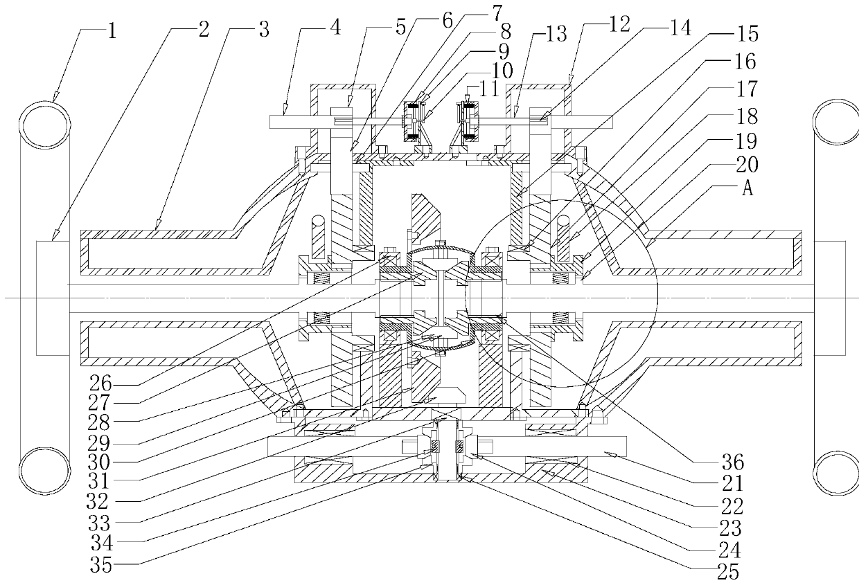
[0005] Aiming at the defect in the prior art that traditional fuel vehicles and new energy vehicles cannot perform normal deceleration and braking after the braking system fails, the applicant designed a new vehicle drive axle, that is, by setting a hollow bridge in the interior as a The main body support, the differential and the two drive shafts are all arranged in the hollow bridge, and when the main brake system of the car fails, the car cannot perform normal braking. At this time, the gear sleeve is driven to move by controlling the shift fork, and The tooth sleeves are respectively meshed with the main teeth and the secondary teeth, and under normal circumstances, the auxiliary brake components that are not connected with the two drive shafts and the differential are linked with each other, that is, the two drive shafts and the differential are rotating. At the same time, the torque is transmitted to the mechanical brake drum through the meshing between the secondary gear and the gear sleeve, the gear sleeve and the main gear, the main gear and the intermediate gear, and the intermediate gear and the generator gear. At the same time, the speed of the drive shaft After being transmitted to the generator teeth through the secondary teeth, gear sleeves, and intermediate teeth, the final mechanical brake drum rotation speed is greatly reduced through a multi-stage differential ratio. Similarly, after the main brake system fails, The driver only needs to perform a small manipulation of the auxiliary braking system to quickly reduce the speed of the drive shaft to achieve emergency braking of the car

Method used


Image

  • A kind of automobile multifunctional driving axle
  • A kind of automobile multifunctional driving axle
  • A kind of automobile multifunctional driving axle

Examples


Embodiment 1

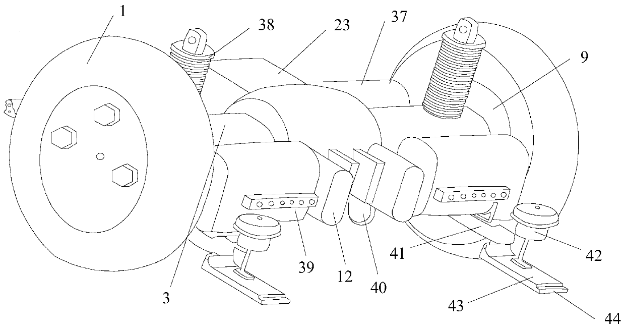
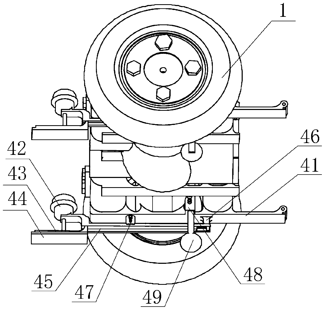
[0028] Such as Figure 1~5 As shown, the present embodiment includes a hollow bridge 3, a differential device arranged inside the hollow bridge 3, and drive shafts 2 respectively arranged at both ends of the differential device. Basin teeth 31 are arranged on the outer wall of the differential device. The outer peripheral wall of each drive shaft 2 is provided with annular secondary teeth 20, and two toothed disc covers 15 are arranged inside the hollow bridge 3, and a bearing I16 is provided on each toothed disc cover 15. , the main tooth 17 is rotatably set in the bearing I16, and two intermediate gear shafts 7 are rotatably arranged inside the hollow bridge 3, and each intermediate gear shaft 7 is fixed with an intermediate tooth 6 that matches the main tooth 17. The outer wall of the hollow bridge 3 is provided with a case cover 12, and the part of the middle tooth 6 runs through the outer wall of the hollow bridge 3 and then extends towards the case cover 12. A mechanical...

Embodiment 2

[0034] Such as Figure 1~3 As shown, on the basis of Embodiment 1, the present embodiment is provided with a driving box cover 23 on the outer wall of the hollow bridge 3, and a central shaft, bearing IV 25 and bearing III 33 are arranged in the driving box cover 23, and the central shaft One end of the shaft is rotated in the bearing IV 25, and the other end of the central shaft passes through the outer wall of the bearing III 33 and the drive box cover 23 and then enters the hollow bridge 3, and the end of the central shaft entering the hollow bridge 3 is fixed with a basin tooth. 31 is matched with the angular gear 32, and a drive gear sleeve 34 is provided in the middle of the central shaft, and the drive planetary gear I 35 is fixed on the drive gear sleeve 34, and drive motors 37 are respectively provided on both sides of the drive case cover 23, and two drive gears The motor drive shaft 21 of the motor 37 respectively penetrates the two side walls of the drive case cove...

Embodiment 3

[0036] Such as Figure 1~2 As shown, on the basis of Embodiment 1, the present embodiment is provided with a pull arm 41 on the lower surface of the hollow bridge 3 , and an adjusting hydraulic cylinder and a straight arm seat 46 are fixed on the bottom of the pull arm 41 . One end is hinged with the straight arm seat 46, and the output end of the adjustment hydraulic cylinder 47 is hinged with the middle part of the straight arm 45. On the other end of the straight arm 45, a brake air pump 42 is installed, and on the output end of the brake air pump 42 An emergency brake plate 43 is connected, and an emergency brake pad 44 is fixed on the lower surface of the emergency brake plate 43 . When the car performs emergency braking, the driver will be injured to a greater extent due to inertial factors, especially when the distance between the car and the car is large and the speed is fast, the main brake system cannot make effective braking, that is, the driving The probability of...


PUM


Abstract

The invention discloses an automobile multifunctional drive axle including a hollow bridge, a differential, and two drive shafts, the outer wall of the differential is provided with basin teeth, a bear is provided on each gear plate cover, the outer wall of the hollow bridge is provided with a box cover, a part of the middle teeth extends through the outer wall of the hollow bridge toward the inside of the box cover, a manipulator brake shaft is rotatably arranged in the box cover, a generator tooth is fixed at one end of the manipulator brake shaft, the other end of the manipulator brake shaft extends outward through the box cover, and a manipulator brake drum is arranged at the extension end of the manipulator brake shaft. The linkage between the drive shaft and the generator shaft is realized by the cooperation of the shift fork and the gear sleeve, in the case of failure of the main brake system of the automobile, the instantaneous stress of the cable in the auxiliary brake systemis prevented from causing the cable to break, the safety factor of the automobile in emergency is greatly improved, and the damage of the driver and the occupant is reduced to the minimum.

Description

technical field [0001] The invention relates to the field of new energy automobiles, in particular to an automobile multifunctional drive axle. Background technique [0002] New energy vehicles refer to the use of unconventional vehicle fuels as power sources (or the use of conventional vehicle fuels, the use of new vehicle power devices), integrated vehicle power control and advanced technology in driving, the formation of advanced technical principles, with Automobiles with new technology and new structure. The drive axle is one of the main components of new energy vehicles. Its function is to bend the power transmitted by the universal transmission through a 90-degree angle, change the direction of force transmission, and reduce the speed by the main differential. After increasing the torque , distributed to the left and right axle shafts and drive wheels through the differential, and when the car encounters an emergency, the driver on the way needs to use the brake syst...

Claims


Application Information

Patent Timeline
Patent Type & Authority Patents(China)
IPC IPC(8): B60K17/04B60T1/06B60T1/14B60S9/205
CPCB60K17/04B60S9/205B60T1/06B60T1/14
Inventor 杜德术杜倩
Owner 杜德术
Learn More