A heating strip and a hot runner and a cold runner structure using the heating strip

A technology of heating strips and hot runners, which is applied in the field of hot runners and cold runners of injection molds, and can solve problems such as the inability to ensure uniform heating of the heating strips, the inability to produce glue, and the inability to ensure the temperature difference between the template 6 of the cold runner.

Active Publication Date: 2021-06-01
苏州泰博特电热科技有限公司
View PDF0 Cites 0 Cited by
  • Summary
  • Abstract
  • Description
  • Claims
  • Application Information

AI Technical Summary

Problems solved by technology

[0002] In the hot runner mold industry, the heating strip used for the hot nozzle is heated in its entirety, and then wound into a heating ring. It is sensitive to the temperature range of plastic material molding, and it is difficult to adjust the temperature. If the temperature is high, it is easy to carbonize, and the temperature is low. No glue, such as Figure 5 As shown, the heating strip is heated as a whole, and then wound into a heating ring 41 and installed on the hot nozzle 4 and put into the mould. Due to the introduction of the temperature of the tip of the nozzle and the hot runner template 5 (manifold plate), the hot nozzle 4 has two upper and lower sides. The end temperature is lower than the middle, and the middle end temperature is higher than the set temperature, so there will be carbonization; Image 6 As shown, in the cold runner mold industry, after the heating strip is installed in the cold runner template 6, the overall temperature of the cold runner template 6 is controlled by a thermocouple, but due to the complex structure of the cold runner template 6, the temperature of the heating strip cannot be guaranteed. Evenly heating it, so that it cannot ensure that the temperature difference between the cold runner template 6 is within 10°C, which will affect the quality of later products

Method used


Image

  • A heating strip and a hot runner and a cold runner structure using the heating strip
  • A heating strip and a hot runner and a cold runner structure using the heating strip
  • A heating strip and a hot runner and a cold runner structure using the heating strip

Examples


Embodiment Construction

[0023] The present invention will be described in further detail below in conjunction with the accompanying drawings.

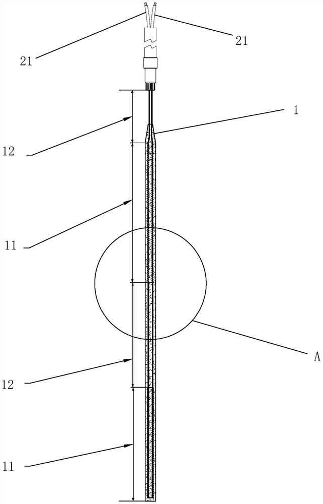
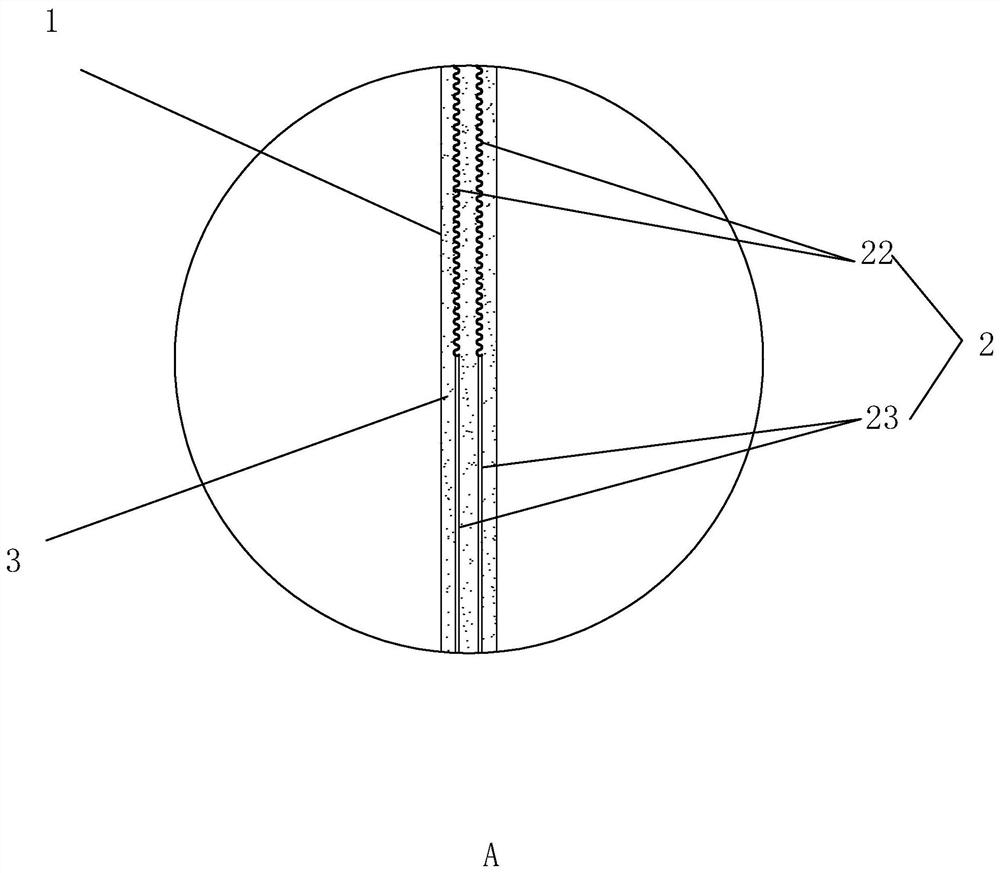
[0024] A heating strip, cf. figure 1 with 2 , which includes a metal capillary 1 and a heating wire 2 located between the metal capillary 1, the metal capillary 1 is made of pure nickel material; the metal capillary 1 is filled with magnesium oxide powder 3, which has the effect of insulating heat conduction; the heating wire 2 is located in the metal capillary Electrodes 21 are provided at both ends of 1 for connecting to the temperature control box, and the heating wire 2 is folded in half inside the metal capillary 1 to form a loop.

[0025] The heating wire 2 includes successively adjacent heating wires 22 and low thermal conductivity wires 23. The heating wire 22 is made of CrNi2080 material, which can generate heat when energized, and the low thermal conductivity wire 23 is made of pure nickel material, which has poor thermal conductivity and relative...


PUM


Abstract

The invention discloses a heating strip, which comprises a metal capillary and a heating wire located between the metal capillary, the metal capillary is filled with magnesium oxide powder, the two ends of the heating wire outside the metal capillary are provided with electrodes, and the heating wire is inside the metal capillary Fold in half and form a loop. The heating wire includes successively adjacent heating wires and low thermal conductivity wires. After the heating wires are folded in half, the heating wires and the low thermal conductivity wires are symmetrical about the folded center line. The metal capillary corresponds to the heating wire and the low thermal conductivity wire. A heating section and a heat conduction section are formed at the position; a hot runner structure includes a hot nozzle and a hot runner template, a heating ring is wound on the hot nozzle, and the heating ring is made of a heating strip; a cold runner structure includes a cold runner The template, the surface of the cold runner template is provided with a temperature control groove, the temperature control groove is embedded with a temperature control strip, and the temperature control strip is made of a heating strip; the technical point is that the length ratio of the heating section and the heat conduction section can be adjusted according to the needs. Meet hot runner, cold runner injection molding needs.

Description

technical field [0001] The invention relates to the technical field of hot runners and cold runners of injection molds, more specifically, it relates to a heating strip and a structure of a hot runner and a cold runner using the heating strip. Background technique [0002] In the hot runner mold industry, the heating strip used for the hot nozzle is heated in its entirety, and then wound into a heating ring. It is sensitive to the temperature range of plastic material molding, and it is difficult to adjust the temperature. If the temperature is high, it is easy to carbonize, and the temperature is low. No glue, such as Figure 5 As shown, the heating strip is heated as a whole, and then wound into a heating ring 41 and installed on the hot nozzle 4 and put into the mould. Due to the introduction of the temperature of the tip of the nozzle and the hot runner template 5 (manifold plate), the hot nozzle 4 has two upper and lower sides. The end temperature is lower than the midd...

Claims


Application Information

Patent Timeline
Patent Type & Authority Patents(China)
IPC IPC(8): B29C45/27
CPCB29C45/2737
Inventor 马杰李洋洋
Owner 苏州泰博特电热科技有限公司
Why Eureka
Try Eureka