Ceramic automatic glazing machine

A technology for automatic glazing and ceramics, which is applied in the field of ceramic processing and can solve problems such as inability to clamp ceramics

Active Publication Date: 2019-01-04
醴陵创智机械有限公司
View PDF8 Cites 9 Cited by
  • Summary
  • Abstract
  • Description
  • Claims
  • Application Information

AI Technical Summary

Problems solved by technology

But this utility model cannot clamp ceramics of different sizes

Method used


Image

  • Ceramic automatic glazing machine
  • Ceramic automatic glazing machine
  • Ceramic automatic glazing machine

Examples


specific Embodiment approach 1

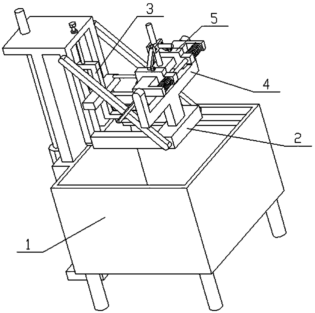
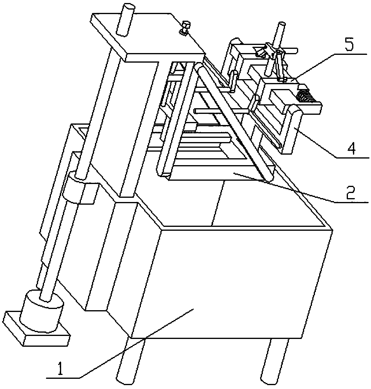
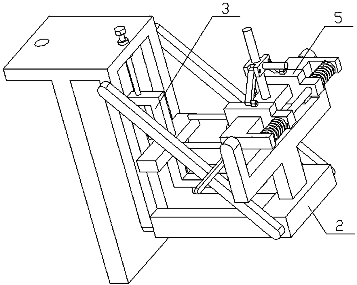
[0028] Combine below Figure 1-11 Describe this embodiment, the present invention relates to the field of ceramic processing, more specifically a kind of ceramic automatic glazing machine, including bottom box assembly 1, lifting frame 2, ceramic bracket 3, fixed carriage 4 and clamping frame 5, When the present invention is used, the bottom of the ceramic needs to be placed on the upper end of the bottom support bar 3-1, and the upper end of the ceramic can be clamped by two clamping rods 5-6, and the present invention can clamp ceramics of different sizes, and the ceramic clamping After the completion, the motor can drive the ceramics to move down and enter the glaze liquid for glazing. After the glazing is completed, the ceramics can be lifted to air dry.

[0029] The lifting frame 2 is slidably connected to the left end of the bottom box assembly 1, the lower end of the ceramic bracket 3 is slidably connected to the lifting frame 2, the upper end of the ceramic bracket 3 i...


PUM


Abstract

The invention relates to the field of ceramic processing, in particular to a ceramic automatic glazing machine. The ceramic automatic glazing machine comprises a bottom box assembly, a lifting frame,a ceramic bracket, a fixing sliding frame and a clamping frame. When the ceramic automatic glazing machine is used, the bottom of ceramic needs to be placed at the upper end of a bottom supporting strip, and two clamping rods can clamp the upper end of the ceramic; and the ceramic automatic glazing machine can clamp the ceramic with different sizes, after being clamped, the ceramic can be driven to downwards move through a motor to enter glaze liquid to be glazed, and after glazing is completed, the ceramic can be lifted and air-dried. The lifting frame is slidably connected to the left end ofthe bottom box assembly; the lower end of the ceramic bracket is slidably connected with the lifting frame; the upper end of the ceramic bracket is matched with the lifting frame through a thread; the fixing sliding frame is fixedly connected to the lifting frame; and the clamping frame is slidably connected to the fixing sliding frame.

Description

technical field [0001] The invention relates to the field of ceramic processing, in particular to a ceramic automatic glazing machine. Background technique [0002] Patent No. CN201621104360.7 is a glazing device for firing ceramics. This utility model discloses a glazing device for firing ceramics. A spring is installed inside the vibrating table, a support rod is connected to the upper surface of the base, a glazing tank is installed on the right side of the support rod, a stirring device is installed inside the glazing tank, and a deceleration device is connected to the upper left side of the support rod. machine, a connecting plate is installed on the upper right side of the support rod, a belt is installed obliquely above the connecting plate, a rotor is connected to the left side of the belt, and a rotary reducer is installed under the connecting plate. A motor is installed on the left side, and a rotating shaft is installed obliquely below the motor, and a bowl blank...

Claims


Application Information

Patent Timeline
IPC IPC(8): B28B11/04
CPCB28B11/044B28B11/045
Inventor 王雨婷
Owner 醴陵创智机械有限公司
Why Eureka
Try Eureka