Steamer cage and a steamer

A technology of steamer and steamer, applied in the field of steamer and steamer, can solve the problems of easy hot hands, inconvenient handling of steamer, etc., and achieve the effects of easy cleaning, improved user experience, and convenient use.

Pending Publication Date: 2019-01-04
GREE ELECTRIC APPLIANCES INC
View PDF2 Cites 1 Cited by
  • Summary
  • Abstract
  • Description
  • Claims
  • Application Information

AI Technical Summary

Problems solved by technology

[0006] Therefore, the present invention aims to solve the technical problems that the existing steamer is inconvenient to take and place, and is easy to burn hands, thereby providing a steamer and a steamer that are easy to take and put and are not easy to burn hands

Method used


Image

  • Steamer cage and a steamer
  • Steamer cage and a steamer
  • Steamer cage and a steamer

Examples


Embodiment 1

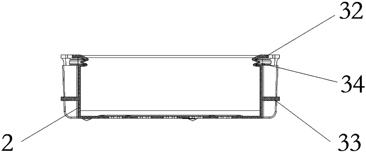
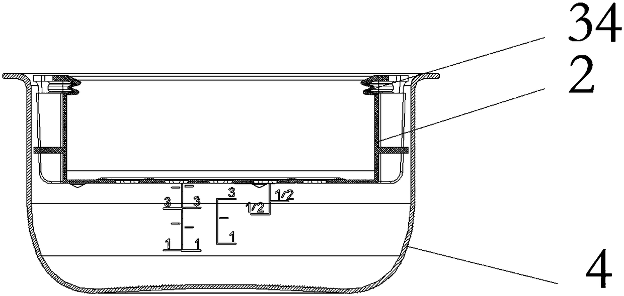
[0049] Such as figure 1 As shown, a steamer provided by the present invention includes: a steaming tray 1 and a cover 2, on which a handle 3 that can protrude from the top of the main body of the steamer where the steamer is located and retract into the main body of the steamer is provided.

[0050] Specifically, such as figure 1 As shown, the steaming tray 1 has a front side and a back side opposite to the front side, wherein the front side is suitable for supporting objects to be steamed. The seal 2 is connected to the edge of the steaming tray 1 and is suitable for sealing the object to be steamed on the front of the steaming tray 1 so that the object to be steamed can escape from the steaming tray 1 . The handle part 3 is located on the block 2 and has at least one set along the circumferential direction of the block 2. The handle part 3 is telescopically arranged along the height direction of the block 2. The handle When the handle part 3 is in the extended state, the h...

Embodiment 2

[0066] Such as Figure 6 As shown in -8, the steamer provided by this embodiment differs from that of Embodiment 1 in that the structure of the elastic deformation part is different. In this embodiment, the elastic deformation part includes: a support section 35, which is bent toward the direction close to the axis of the steamer when the cover of the steamer is pressed down; When the pressure disappears, the supporting section 35 returns to the opposite direction of the bending direction. The support section 35 can be inclined towards the axis of the steamer under the action of the cover of the steamer. At this time, the length of the support section 35 along the height direction of the steamer is shortened compared to when the support section 35 is straightened; when the pressure disappears, The supporting section 35 straightens, and at this moment, the supporting section 35 is in an elongated state.

[0067] Further, such as Figure 6 and Figure 7 As shown, in the pres...

Embodiment 3

[0069] This embodiment provides a steamer, which has the steamer described in Embodiment 1 or 2.


PUM


Abstract

The invention provides a steamer cage and a steamer, which solve the technical problems that the existing steamer is inconvenient to take and put and is easy to burn hands. The steamer cage comprisesa steamer disc provided with a front side supporting an object to be steamed and a reverse side opposite to the front side; a sealing block connected to the edge of the steam tray, and adapted to sealthe object to be steamed on the front side of the steam tray; at least one set of handle part arranged on that seal and along the circumferential direction of the seal, wherein the handle parts are telescopically arranged along the height direction of the seal, and when the handle part is in an extended state, the portable part of the handle part is higher than the top of the steam appliance mainbody in which the steamer cage is located. When the handle part is pressed down by the steam appliance cover, the portable part is retracted into the steam appliance main body. A folding handle partis arranged on the sealing block of the steamer cage, so that the space of the steamer cage handle holding part is changeable, and the handle state changes in the process of opening and closing the lid of the steamer cage, so as to meet the requirements of different users on the handle, and improve the user experience.

Description

technical field [0001] The invention relates to the technical field of cooking utensils, in particular to a steamer and a steamer. Background technique [0002] Steaming is an important cooking method, and most of the food of Chinese residents is cooked by steaming. Steaming is heating with steam, which maintains the prototype, original juice and original flavor of the dish, and can preserve various nutrients of the dish to a large extent. When steaming food, it is necessary to use a matching steamer and a steamer, place the food in the steamer, and steam for a certain period of time under the action of the steam in the steamer to cook the food. At present, electric rice cookers on the market are all equipped with steamers when they are sold. However, during the use of the existing steamers, there are generally disadvantages such as inconvenient taking and placing of the steamers, easy scalding, and too many structural dead spots that are difficult to clean. [0003] For e...

Claims


Application Information

Patent Timeline
Patent Type & Authority Applications(China)
IPC IPC(8): A47J27/04A47J27/16A47J36/20A47J36/00
CPCA47J27/04A47J27/16A47J36/00A47J36/20A47J2027/043
Inventor 陈亮陈伟张源智高塬贵康津潘泽勇邓志宏乡志祥李锦彬夏鹏李磊
Owner GREE ELECTRIC APPLIANCES INC
Why Eureka
Try Eureka