Handtool with improved gas combustion

A hand-held tool and gas technology, applied in the direction of gas fuel burners, burners, combustion methods, etc., can solve the problems of expensive and inconvenient tools

Inactive Publication Date: 2012-11-21
GUILBERT EXPRESS
View PDF0 Cites 0 Cited by
  • Summary
  • Abstract
  • Description
  • Claims
  • Application Information

AI Technical Summary

Problems solved by technology

However these tools are still inconvenient and very expensive

Method used


Image

  • Handtool with improved gas combustion
  • Handtool with improved gas combustion
  • Handtool with improved gas combustion

Examples


Embodiment Construction

[0034] The accompanying drawings will not only serve to supplement the invention, but also contribute to the description of the invention where necessary.

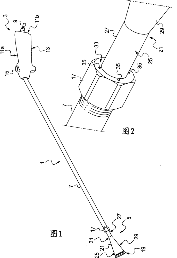
[0035] figure 1 A flame spray gun 1 is shown as an example of a gas combustion hand tool embodying the invention.

[0036] The flame spray gun 1 basically comprises a grip handle 3 and a gas burner 5 , which are connected to each other by a gas flow pipe 7 .

[0037] The handle 3 can be connected to a gas source through a gas connector 9, the pressure of the gas source is reduced to the required operating pressure, and the gas connector 9 is arranged to receive the end of a hose (not shown) connected to the gas source (not shown) .

[0038] The handle 3 comprises in particular a grip sleeve. This sleeve comprises an upper part 11a designed to accommodate the palm of the user and a lower part 11b from which a control lever 13 protrudes downwards, enabling the actuation of a gas supply (not shown) located in the handle 3 ...


PUM


Abstract

Provided is a burner (5) for a gas burning hand tool (1), of the type comprising an elongated burner body (21), associated at opposite ends of the body with a gas injection zone (17) and a gas combustion zone (19). The gas injection zone (17) comprises at least one outlet orifice (35) terminating flush on the outside of the periphery (25) of the burner body (21), this periphery (25) promoting thecirculation of the gas outside the burner body (21) to the combustion zone (19). Gas burning hand tool equipped with a burner of this type is also provided.

Description

technical field [0001] The present invention relates to the field of hand tools for improved gas combustion. Background technique [0002] In this type of tool, gas combustion is used to generate the flame, which constitutes the effective element of the tool. [0003] There are currently several varieties of tools of this type. For example, in a spray welder, the flame is primarily used for cutting or welding. In spray guns, flames are commonly used to heat various types of work surfaces. [0004] For example, spray guns are commonly used to heat and thereby attach strips used to mark sidewalks on highways. [0005] These spray guns are therefore also useful in operations involving the removal of films of plastics material by heating them. [0006] A number of other fields are therefore involved. Membranes of this type are used, for example, to cover yachts when they are taken out of the water, such as during winter, and these films can also be used to protect civil eng...

Claims


Application Information

Patent Timeline
Patent Type & Authority Patents(China)
IPC IPC(8): F23D14/00
CPCF23D14/52
Inventor D·布维耶Y·吉尤C·勒德拉皮耶L·塔凯拉
Owner GUILBERT EXPRESS
Why Eureka
Try Eureka