
Mobile terminal antenna multiplexing system and control method thereof and mobile terminal

A mobile terminal antenna and control method technology, which is applied in the field of communication, can solve the problems of adding mobile terminals, few multi-feed point multiplexing antennas, etc., and achieve the effect of reasonable utilization, improved frequency coverage and transceiver performance

Active Publication Date: 2019-01-01
GREE ELECTRIC APPLIANCES INC
View PDF5 Cites 13 Cited by
  • Summary
  • Abstract
  • Description
  • Claims
  • Application Information

AI Technical Summary

Problems solved by technology

However, the design space of the terminal antenna has not increased. On the contrary, the current popular design schemes such as full screen and all-metal back cover further reduce the design space of the antenna and deteriorate the antenna radiation environment. However, in the case where the mobile communication frequency does not change Under the current situation, it is unrealistic to greatly increase the number of antennas on the mobile terminal. At present, the commonly used antenna multiplexing scheme includes antenna tuning, but there are few schemes that use multiple feed points to multiplex antennas.

Method used


Image

  • Mobile terminal antenna multiplexing system and control method thereof and mobile terminal
  • Mobile terminal antenna multiplexing system and control method thereof and mobile terminal

Examples


Embodiment Construction

[0022] The present invention will be further described below through specific embodiments.

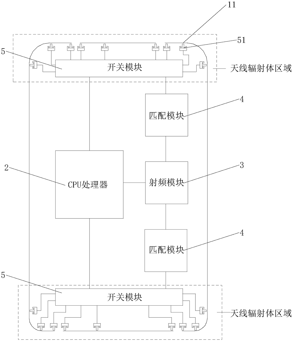
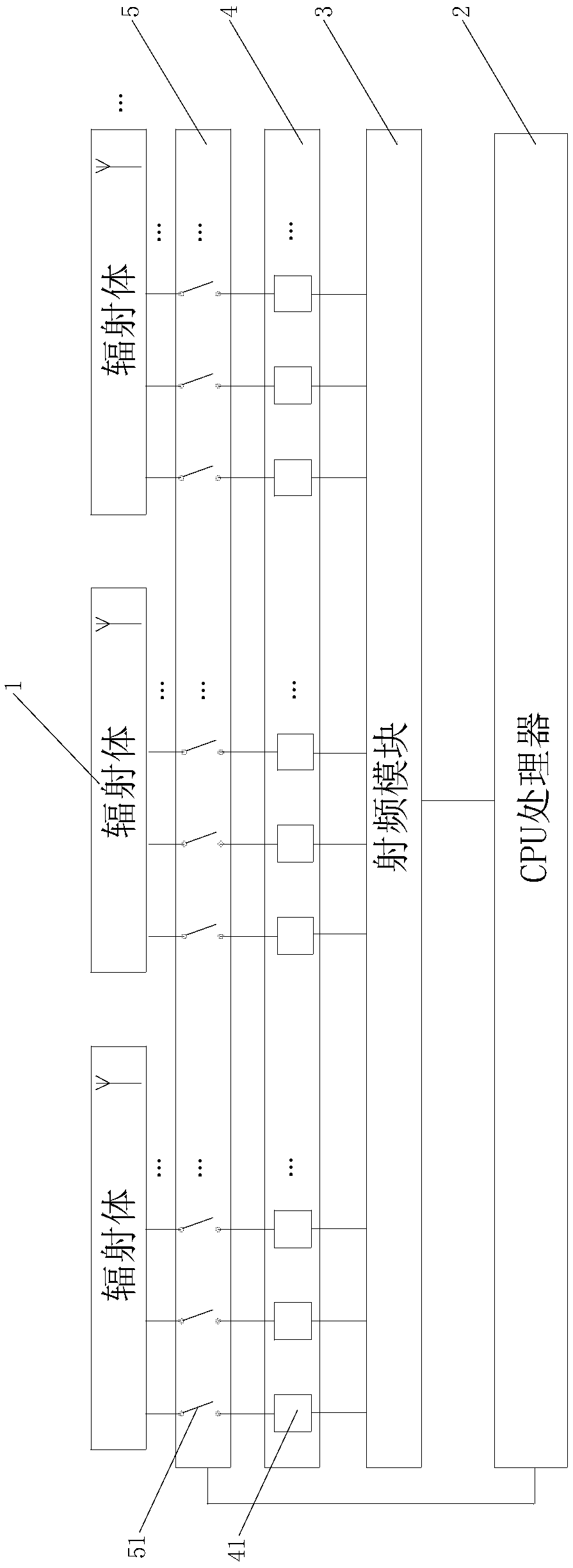
[0023] Such as figure 1 , figure 2 As shown, a mobile terminal antenna multiplexing system includes a radiator 1, multiple antenna paths, a CPU processor 2, and a radio frequency module 3. The antenna path includes a feed point 11, a matching module 4, and a switch module 5. The feeding point 11 includes multiple, connected to the radiator 1; the matching module 4 includes a plurality of matching units 41 corresponding to the feeding point 11, and the matching unit 41 is connected to the feeding point 11 through a matching circuit , used to adjust the characteristic impedance of the antenna path; the switch module 5 includes a plurality of switches 51 corresponding to the feed point 11, and the switches 51 are arranged on the matching circuit to control the on-off of the antenna path; the switch 51 It is a numerically controlled switch; the CPU processor 2 is used to coordinate the ...


PUM


Abstract

The present invention discloses a mobile terminal antenna multiplexing system and a control method thereof and a mobile terminal. The mobile terminal antenna multiplexing system comprises a radiatingbody, multiple antenna accesses, a CPU processor and a radio frequency module, each antenna access comprises one feed point, one matching module and one switching module. The antenna radiating body ofthe mobile terminal is provided with a plurality of feed points, each feed point is connected with one switch, the each feed point is provided with one independent matching circuit, the mobile terminal controls the on-off switch of the switch through the CPU processor according to the concrete application demand and the environmental state of the mobile terminal so as to change the resonant frequency of the corresponding antenna, corresponding antenna accesses are selected through the radio frequency modules to achieve antenna multiplexing. On the premise without increasing the number of themobile terminal antennas, the mobile terminal antenna radiators can be more intelligently and reasonably utilized, and the frequency coverage and the receiving and transmission performances of the mobile terminal antennas are improved.

Description

technical field [0001] The present invention relates to the field of communication technology, in particular to a mobile terminal antenna multiplexing system, a control method and a mobile terminal thereof. Background technique [0002] With the advent of the 5G era, the demand for antennas in the field of mobile terminals is also increasing, which is specifically reflected in the need for wider coverage frequencies and more antennas. However, the design space of the terminal antenna has not increased. On the contrary, the current popular design schemes such as full screen and all-metal back cover further reduce the design space of the antenna and deteriorate the antenna radiation environment. However, in the case where the mobile communication frequency does not change Under the circumstances, it is unrealistic to greatly increase the number of antennas on the mobile terminal. At present, the commonly used antenna multiplexing scheme includes antenna tuning, but there are f...

Claims


Application Information

Patent Timeline
Patent Type & Authority Applications(China)
IPC IPC(8): H04B1/00H01Q1/36H01Q1/50
CPCH01Q1/36H01Q1/50H04B1/006
Inventor 胡勋强
Owner GREE ELECTRIC APPLIANCES INC
Learn More