
Biasing circuit

A bias circuit and bias current technology, applied in the direction of adjusting electrical variables, control/regulation systems, instruments, etc., can solve problems such as failure to meet requirements, and achieve the effect of small area

Active Publication Date: 2019-01-01
GIANTEC SEMICON LTD
View PDF3 Cites 3 Cited by
  • Summary
  • Abstract
  • Description
  • Claims
  • Application Information

AI Technical Summary

Problems solved by technology

The PSRR cannot meet the requirements in many high-precision circuits

Method used


Image

  • Biasing circuit
  • Biasing circuit
  • Biasing circuit

Examples


Embodiment Construction

[0072] based on the following Figure 4 ~ Figure 11 , specifically explain the preferred embodiment of the present invention.

[0073] Such as Figure 4 As shown, the present invention provides a bias circuit, comprising:

[0074] A positive temperature coefficient bias current generation circuit that generates a bias current I with a positive temperature coefficient B1 ;

[0075] A negative temperature coefficient bias current generation circuit that generates a bias current I with a negative temperature coefficient B2 ;

[0076] A constant temperature voltage generating circuit that generates a bias current I with a positive temperature coefficient B1 and negative temperature coefficient bias current I B2 The associated constant temperature voltage Vref;

[0077] A constant temperature current generation circuit that generates a bias current with a positive temperature coefficient I B1 and negative temperature coefficient bias current I B2 The associated constant te...


PUM


Abstract

Disclosed is a biasing circuit. The biasing circuit comprises a positive temperature coefficient bias current generating circuit, a negative temperature coefficient bias current generating circuit, aconstant temperature voltage generating circuit and a constant temperature current generating current, wherein the positive temperature coefficient bias current generating circuit is used for generating a biasing current IB1 with a positive temperature coefficient; the negative temperature coefficient bias current generating circuit is used for generating a biasing current IB2 with a negative temperature coefficient; the constant temperature voltage generating current is used for generating a constant temperature voltage Vref related to the positive temperature coefficient biasing current IB1and the negative temperature coefficient biasing current IB2; and the constant temperature current generating current is used for generating a constant temperature current Iref related to the positivetemperature coefficient biasing current IB1 and the negative temperature coefficient biasing current IB2. By virtue of the biasing circuit, a voltage source and a current source can be generated at the same time, and the biasing circuit has the advantage of a small area as a CMOS biasing circuit as well as high PSRR and low low-temperature drift characteristics as a traditional Bipolar circuit.

Description

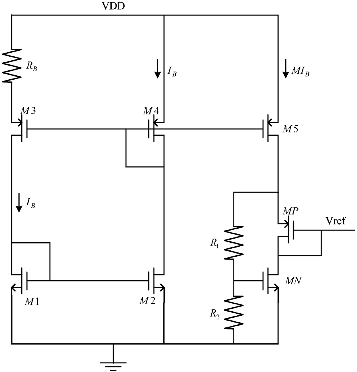
technical field [0001] The invention relates to the field of integrated circuits, in particular to a bias circuit capable of simultaneously generating a constant temperature current source and a constant temperature voltage source. Background technique [0002] With the development of integrated circuits, the chip area is gradually reduced. Bias voltage source and bias current source are two essential signal sources in the operation of analog integrated circuits. In the traditional design, the bipolar (bipolar) tube is used to generate bias voltage and bias current. Although better PSRR and better temperature drift characteristics can be obtained, it occupies a large area of ​​the circuit. The bias circuit designed with pure CMOS devices can effectively save the circuit area, but its PSRR and temperature drift performance are relatively poor. [0003] figure 1 It is a common bias circuit designed by pure CMOS devices. In this circuit, M1~M4 tubes and resistor R B Generat...

Claims


Application Information

Patent Timeline
Patent Type & Authority Applications(China)
IPC IPC(8): G05F1/56
CPCG05F1/56
Inventor 陈珍珍汤浩张洪杨清
Owner GIANTEC SEMICON LTD
Learn More