
Liquid crystal optical waveguide and laser radar

A laser radar and optical waveguide technology, applied in the field of radar, can solve the problems of low scanning speed, limited scanning range, and reduced scanning accuracy, and achieve the effect of increasing the scanning angle

Pending Publication Date: 2019-01-01
SUTENG INNOVATION TECH CO LTD
View PDF0 Cites 10 Cited by
  • Summary
  • Abstract
  • Description
  • Claims
  • Application Information

AI Technical Summary

Problems solved by technology

However, both the first and second ways of controlling the change of the beam are heavily affected by mechanical movement, resulting in reduced scanning accuracy
At the same time, although the third way to control the change of the beam has no mechanical movement, it has the disadvantages of limited scanning range and low scanning speed.

Method used

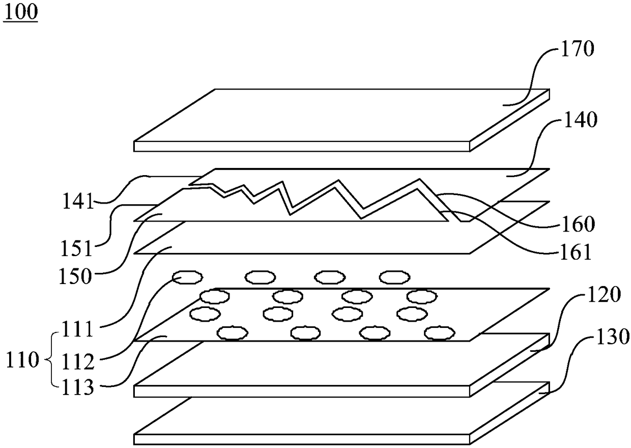
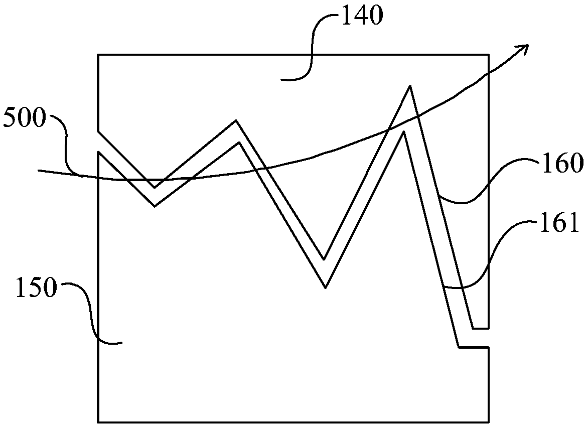
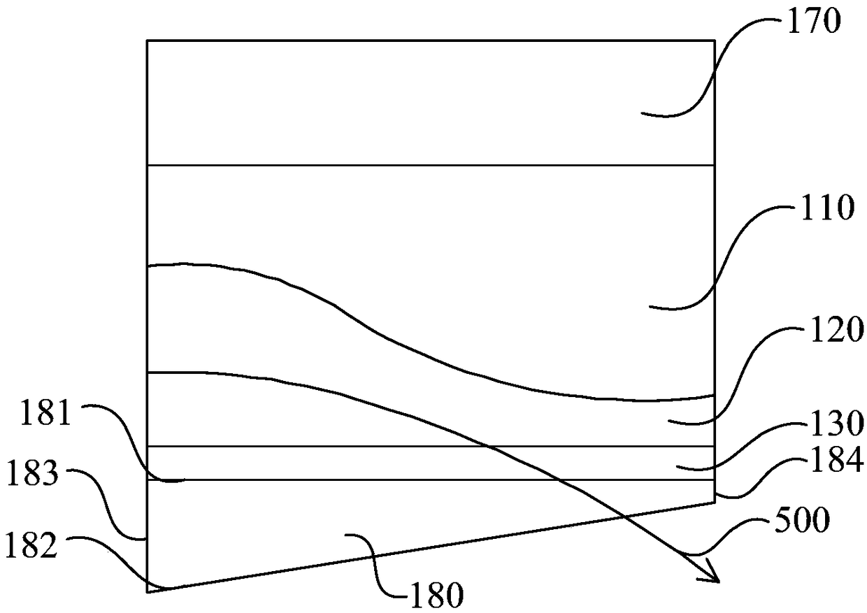

Image

  • Liquid crystal optical waveguide and laser radar
  • Liquid crystal optical waveguide and laser radar
  • Liquid crystal optical waveguide and laser radar

Examples


Embodiment Construction

[0026] In order to make the object, technical solution and advantages of the present invention clearer, the present invention will be further described in detail below in conjunction with the accompanying drawings and specific implementation methods. It should be understood that the specific embodiments described here are only used to explain the present invention, and do not limit the protection scope of the present invention.

[0027] It should be noted that when an element is referred to as being “fixed” to another element, it can be directly on the other element or there can also be an intervening element. When an element is referred to as being "connected to" another element, it can be directly connected to the other element or intervening elements may also be present. The terms "vertical," "horizontal," "left," "right," and similar expressions are used herein for purposes of illustration only and are not intended to represent the only embodiments.

[0028] Unless otherw...


PUM


Abstract

The invention discloses a liquid crystal optical waveguide and laser radar. The liquid crystal optical waveguide comprises a liquid crystal assembly, a waveguide core, a cladding layer and a first conductive film. When the first conductive film is not connected with a first electrode, the waveguide core is in a mode guiding mode, and therefore, when the laser beams enter the waveguide core, the laser beams can carry out total reflection propagation in the waveguide core. Due to the fact that the first conductive film is arranged on one side of the liquid crystal assembly, when the first conductive film is connected with the first electrode, the liquid crystal assembly is in an electric field, so that the liquid crystal molecules can be re-ordered under the action of the electric field, andthe refractive index of the liquid crystal assembly is changed, and at the moment, the waveguide core is in a radiation mode state. When the laser beams are emitted into the waveguide core, the laserbeams can be refracted into the liquid crystal assembly, and the original laser beams can be deflected under the action of the liquid crystal molecules, so that the laser beams can be emitted at different angles, and therefore, the laser beams can complete scanning of the plane direction of the vertical waveguide core.

Description

technical field [0001] The invention relates to the technical field of radar, in particular to a liquid crystal optical waveguide and laser radar. Background technique [0002] Lidar is a system that emits laser beams to detect characteristic quantities such as the position and speed of targets, and is widely used in the field of laser detection. In order to adapt to two-dimensional and / or three-dimensional detection, it is usually adopted to keep the lidar itself stationary or relatively stationary, so that the beam emitted by the lidar changes. [0003] There are generally three traditional laser radar beam control methods: the first is to use mechanical components for beam deflection scanning; the second is to use MEMS (Micro-Electro-Mechanical System for Micro-Electro-Mechanical System) vibrating mirrors for scanning; the third is Beam deflection using an optical phased array. However, both the first and the second ways of controlling the change of the light beam are s...

Claims


Application Information

Patent Timeline
Patent Type & Authority Applications(China)
IPC IPC(8): G02F1/13G02F1/1337G02F1/1343G02F1/295
CPCG02F1/1313G02F1/1337G02F1/134309G02F1/295
Inventor 邱纯鑫刘乐天
Owner SUTENG INNOVATION TECH CO LTD
Learn More