
Novel frequency detection resonant magnetometer

A magnetometer and resonant technology, applied in the direction of the magnitude/direction of the magnetic field, can solve the problems of injecting large current and low linearity, and achieve the effects of reducing operating current, low manufacturing cost, and improving linearity

Active Publication Date: 2019-01-01
CHINA RESOURCES MICROELECTRONICS (CHONGQING) CO LTD
View PDF4 Cites 0 Cited by
  • Summary
  • Abstract
  • Description
  • Claims
  • Application Information

AI Technical Summary

Problems solved by technology

[0004] The technical problem to be solved by the present invention is to provide a new type of frequency detection resonant magnetometer to solve the technical problems that the magnetometer in the prior art needs to inject a large current and have low linearity when it works

Method used


Image

  • Novel frequency detection resonant magnetometer
  • Novel frequency detection resonant magnetometer

Examples


Embodiment 1

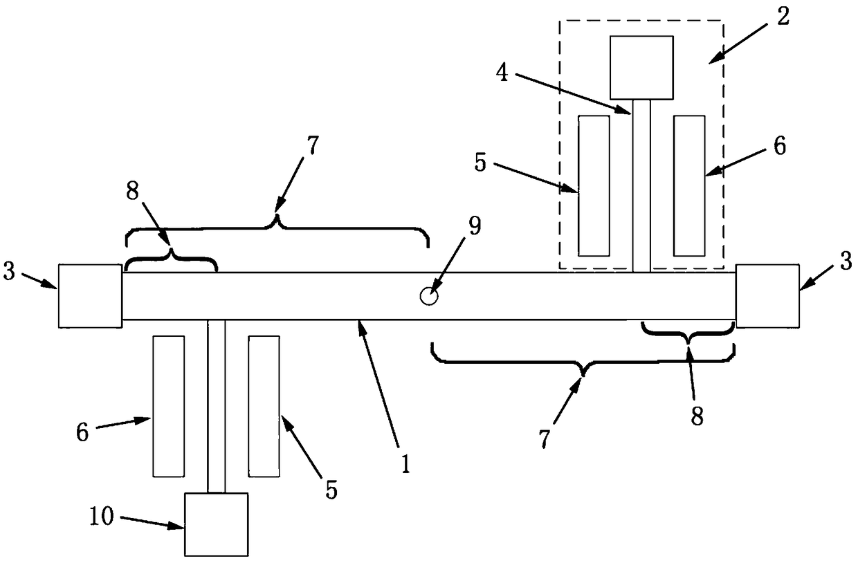
[0024] Embodiment 1 provides a novel frequency detection resonant magnetometer, comprising a sensitive beam 1 and at least one pair of beam resonators 2, and the two ends of the sensitive beam 1 are respectively fixed on a first anchor point 3;

[0025] Each pair of beam resonators 2 includes a beam resonator 2 arranged on the first surface of the sensitive beam 1 and a beam resonator 2 arranged on the second surface of the sensitive beam, and the two beams The resonators 2 are respectively arranged at both ends of the sensitive beam 1;

[0026] Each beam resonator 2 includes a resonant beam 4, a driving part 5 and a detection part 6, the driving part 5 is used to drive the beam resonator 2 to work, and the detection part 6 is used to detect the The resonant frequency of the beam resonator 2 is described above. One end of the resonant beam 4 is vertically fixed on the sensitive beam 1 , and the other end of the resonant beam 4 is fixed on a second anchor point 10 .

[0027] ...

Embodiment 2

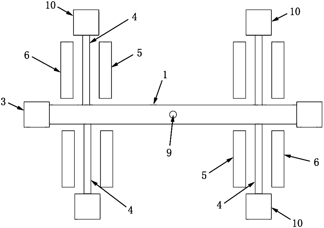
[0033] The difference between Embodiment 2 and Embodiment 1 is that in Embodiment 2, the number of beam resonators 2 is two pairs, that is, there are four beam resonators 2, which are arranged on the same sensitive beam in different pairs. The beam resonators 2 on the surface are respectively arranged at both ends of the sensitive beam 1 . Specifically, the four beam resonators 2 are arranged symmetrically on the sensitive beam 1 , that is, the horizontal distance between each beam resonator 2 and the central point 9 of the sensitive beam 1 is the same.


PUM


Abstract

The invention discloses a novel frequency detection resonant magnetometer, which comprises a sensitive beam and at least one pair of beam resonators, wherein two ends of the sensitive beam are respectively fixed on first anchor points; each pair of beam resonators includes a beam resonator arranged on a first side of the sensitive beam and a beam resonator arranged on a second side of the sensitive beam, and the two beam resonators are respectively arranged at two ends of the sensitive beam; and each beam resonator comprises a resonant beam, a driving component used for driving the beam resonator to operate and a detecting component used for detecting the resonant frequency of the beam resonator, one end of the resonator beam is vertically fixed on the sensitive beam, and the other end ofthe resonator beam is fixed on a second anchor point. The novel frequency detection resonant magnetometer solves a technical problem that the magnetometer in the prior art needs high current injectionin operation and is low in linearity.

Description

technical field [0001] The invention relates to the technical field of sensor manufacturing, in particular to a novel frequency detection resonant magnetometer. Background technique [0002] A resonant sensor is a sensor that uses a resonant element to convert the measured parameter into a frequency signal, also known as a frequency sensor. When the measured parameter changes, the natural vibration frequency of the vibrating element changes accordingly, and through the corresponding measurement circuit, an electrical signal that has a certain relationship with the measured parameter can be obtained. Resonant sensors can be divided into vibrating wire, vibrating cylinder, vibrating beam, diaphragm and piezoelectric resonance, etc. Resonant sensors are mainly used to measure pressure, but also to measure torque, density, acceleration and temperature, etc. . [0003] At present, most of the research on the resonant magnetometer focuses on the direction of amplitude detection,...

Claims


Application Information

Patent Timeline
Patent Type & Authority Applications(China)
IPC IPC(8): G01R33/02
CPCG01R33/02
Inventor 焦文龙闫旭亮李君儒
Owner CHINA RESOURCES MICROELECTRONICS (CHONGQING) CO LTD
Learn More