A combined photothermal aging test device for power equipment
A technology of photothermal aging and test device, applied in the direction of measuring device, measuring electricity, measuring electrical variables, etc., can solve the problem of no photothermal aging test device, etc., and achieve the effect of saving energy
- Summary
- Abstract
- Description
- Claims
- Application Information
AI Technical Summary
Problems solved by technology
Method used
Image


Examples
Embodiment 1
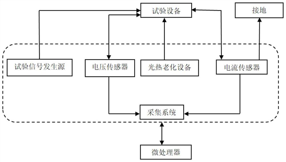
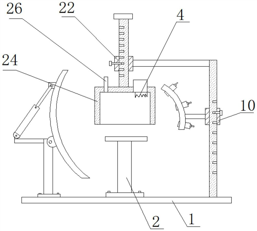
[0029] see Figure 1~6 , the present invention provides a technical solution: a combined photothermal aging test device for power equipment, including a test signal generation source, a photothermal aging device, a current sensor, a voltage sensor, an acquisition system and a microprocessor, the microprocessor The data signal connection between the device and the test signal generation source, the photothermal aging device, the current sensor, the voltage sensor, and the acquisition system; the photothermal aging device includes a base 1, and the top of the base 1 is fixed with a first support column by screws 2. The top of the first support column 2 is welded with an equipment support plate 3, and the top left side of the base 1 is fixed with a second support column 5 by screws, and the top of the second support column 5 is hinged to the first concave surface The outer side of the concentrator 8, the outer side of the second support column 5 is welded with a first beam 6, the...
Embodiment 2
[0041] Embodiment 2 Electrothermal aging test
[0042] The test equipment is a 10kV cable, the test signal generator provides a voltage of 10kV, 50Hz, and the far end of the cable is connected to a 2k ohm load. The cable length is 50 meters, and the cable is passed through the transparent box body 24 at the middle position, and the temperature of the transparent box body is adjusted to 150 degrees, and the setting time is 60 minutes.
[0043] The acquisition system collects the loop current through the core current transformer, collects the cable terminal voltage through the step-down voltage converter, and records the waveform value, effective value, and phase of current and voltage. Assume that the acquisition system collects data once every 5 minutes to obtain the phase-time characteristic curve, see Figure 7 .
[0044] Since the temperature applied by high temperature aging is the limit temperature of the cable, the local aging of the cable will be intensified. If one h...
Embodiment 3
[0045] Embodiment 3 Photo-electricity-thermal aging test
[0046] The test equipment is a 10kV cable, and the test signal generator provides a voltage of 10kV, 50Hz. In this test, a photothermal aging heating with a length of 3 meters is carried out at a distance of 60 meters of cable. The concentrating power of the concentrator is set to 20 times, and the surface temperature of the cable at the concentrating position reaches 150 degrees. Such as Figure 8 As shown, under the effect of spotlight, after the same 60 minutes, even if only the 3-meter-long cable is heated in the spotlight mode, the influence on the overall impedance angle is very obvious. When other conditions are the same as the experimental conditions of Example 2, the obtained impedance angle curve is tested.
[0047] Such as Figure 8 As shown, under the effect of spotlight, after the same 60 minutes, even if only the 3-meter-long cable is heated in the spotlight mode, the influence on the overall impedanc...
PUM
| Property | Measurement | Unit |
|---|---|---|
| length | aaaaa | aaaaa |
Abstract
Description
Claims
Application Information
 - R&D
- Intellectual Property
- Life Sciences
- Materials
- Tech Scout
- Unparalleled Data Quality
- Higher Quality Content
- 60% Fewer Hallucinations
Browse by: Latest US Patents, China's latest patents, Technical Efficacy Thesaurus, Application Domain, Technology Topic, Popular Technical Reports.
© 2025 PatSnap. All rights reserved.Legal|Privacy policy|Modern Slavery Act Transparency Statement|Sitemap|About US| Contact US: help@patsnap.com