
Elevator shaft beam for pulling upper telescopic construction lifting machine and installation and use method thereof

A technology for construction elevators and elevator shafts, which is applied to elevators, transportation, and packaging in buildings. It can solve the problems of increasing the amount of wire ropes, wasting manpower and material resources, and unable to guarantee the construction period, so as to reduce labor intensity, save energy, and have novel designs. Effect

Pending Publication Date: 2019-01-01
河南海恒机械设备有限公司
View PDF7 Cites 5 Cited by
  • Summary
  • Abstract
  • Description
  • Claims
  • Application Information

AI Technical Summary

Problems solved by technology

[0002] In the construction of high-rise buildings, construction hoists for elevator shafts are usually used. One is to set the traction machine on the ground, and the other is to use a straight beam. This kind of traction machine is set on the ground, and the wire rope can be guided by 7 guide wheels. The car and the counterweight also increase the amount of steel wire ropes. During the use of the in-line integral beam, the installation and later heightening of the in-line integral beam caused a lot of inconvenience due to the excessive length of the beam body. During the operation, the beam body should be hung obliquely and inserted into the reserved hole, which is inconvenient and unsafe to operate, and a horse stool with a height of 1500mm should be supported under the sky beam, which cannot be supported. The tight connection with the Tianliang is unstable, and the 1500mm horse stool weighs 80kg, which has to be carried repeatedly by manpower on the shoulders. The speed is too slow, which not only wastes manpower and material resources, but also cannot guarantee the construction period.

Method used


Image

  • Elevator shaft beam for pulling upper telescopic construction lifting machine and installation and use method thereof
  • Elevator shaft beam for pulling upper telescopic construction lifting machine and installation and use method thereof
  • Elevator shaft beam for pulling upper telescopic construction lifting machine and installation and use method thereof

Examples


Embodiment Construction

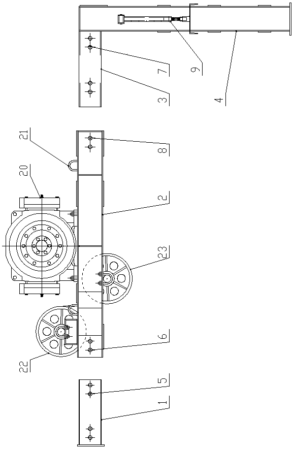
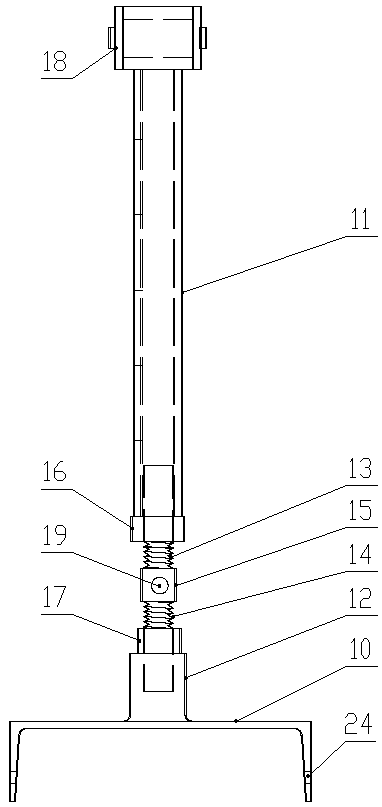
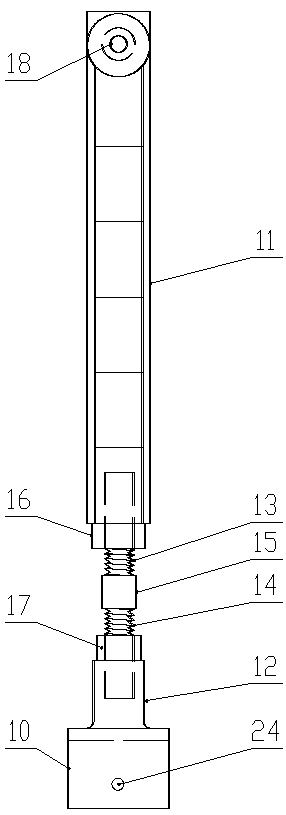
[0038] Such as figure 1 , figure 2 and image 3 As shown, the elevator shaft traction upper telescopic construction hoist sky beam of the present invention comprises a left telescopic short beam 1, a main beam 2, a right telescopic short beam 3 and a pillar beam 4, a left telescopic short beam 1, a main beam 2 and a The right telescopic short beam 3 is arranged along the horizontal direction, and the pillar beam 4 is arranged along the vertical direction. The upper end of the pillar beam 4 is fixedly connected with the right end of the right telescopic short beam 3 to form an L-shaped structure; Folding positioning bar 9;

[0039] The main beam 2 is welded by two 20# channel steels with opposite openings, and the left telescopic short beam 1, the right telescopic short beam 3 and the pillar beam 4 are all welded by two 18# channel steels with opposite openings;

[0040] The left telescopic short beam 1 is inserted inside the left end of the main beam 2. The left telescopi...


PUM


Abstract

The invention relates to an elevator shaft beam for pulling an upper telescopic construction lifting machine. The elevator shaft beam for pulling the upper telescopic construction lifting machine comprises a left telescopic short beam, a main beam, a right telescopic short beam and a support beam, wherein the upper end of the support beam is fixedly connected with the right end of the right telescopic short beam so as to form an L-shaped structure; two groups of folding and positioning rod pieces are rotatably connected to the front side and the back side of the support beam respectively; theleft telescopic short beam is inserted into the left end of the main beam; and the right telescopic short beam is inserted into the right end of the main beam. The invention further discloses an installation and use method of the elevator shaft beam for pulling the upper telescopic construction lifting machine, compared with a conventional installation method, the installation and use method has the advantages of novel design, convenience in use, rapidity, easiness in operation, convenience, energy conservation, environmental friendliness and high practicability and is worthy of popularization, and the use mode of a traction machine is expanded.

Description

technical field [0001] The invention belongs to the technical field of building construction machinery and equipment, and in particular relates to an elevator shaft traction top-mounted retractable construction hoist sky beam and an installation and use method thereof. Background technique [0002] In the construction of high-rise buildings, construction hoists for elevator shafts are usually used. One is to set the traction machine on the ground, and the other is to use a straight beam. This kind of traction machine is set on the ground, and the wire rope can be guided by 7 guide wheels. The car and the counterweight also increase the amount of steel wire ropes. During the use of the in-line integral beam, the installation and later heightening of the in-line integral beam caused a lot of inconvenience due to the excessive length of the beam body. During the operation, the beam body should be hung obliquely and inserted into the reserved hole, which is inconvenient and unsa...

Claims


Application Information

Patent Timeline
IPC IPC(8): B66B11/00
CPCB66B11/0045Y02B50/00
Inventor 谢利明崔文才
Owner 河南海恒机械设备有限公司
Learn More