
Rapid feeding mechanism of shaft workpiece

A shaft workpiece and feeding mechanism technology, applied in the direction of conveyors, transportation and packaging, etc., can solve the problems of basic workpiece interference, axially extending body stuck to the vibrating plate, poor effect, etc., to solve the difficulty of feeding , the effect of fast and orderly arrangement

Pending Publication Date: 2019-01-01
JIANGSU XINTIMU INTELLIGENT EQUIP CO LTD
View PDF0 Cites 2 Cited by
  • Summary
  • Abstract
  • Description
  • Claims
  • Application Information

AI Technical Summary

Problems solved by technology

The current effective method is to use a vibrating plate to complete, but this form is not suitable for shaft workpieces with a long length. The axially extending body often jams the vibrating plate or the basic workpiece. They will also interfere with each other without forming an orderly arrangement on the vibrating plate
Furthermore, when the feeding area includes a height difference, the conveying process is more difficult and the effect is even worse

Method used


Image

  • Rapid feeding mechanism of shaft workpiece
  • Rapid feeding mechanism of shaft workpiece
  • Rapid feeding mechanism of shaft workpiece

Examples


Embodiment Construction

[0022] In order to enable those skilled in the art to better understand the technical solutions of the present invention, the present invention will be further described in detail below in conjunction with specific embodiments.

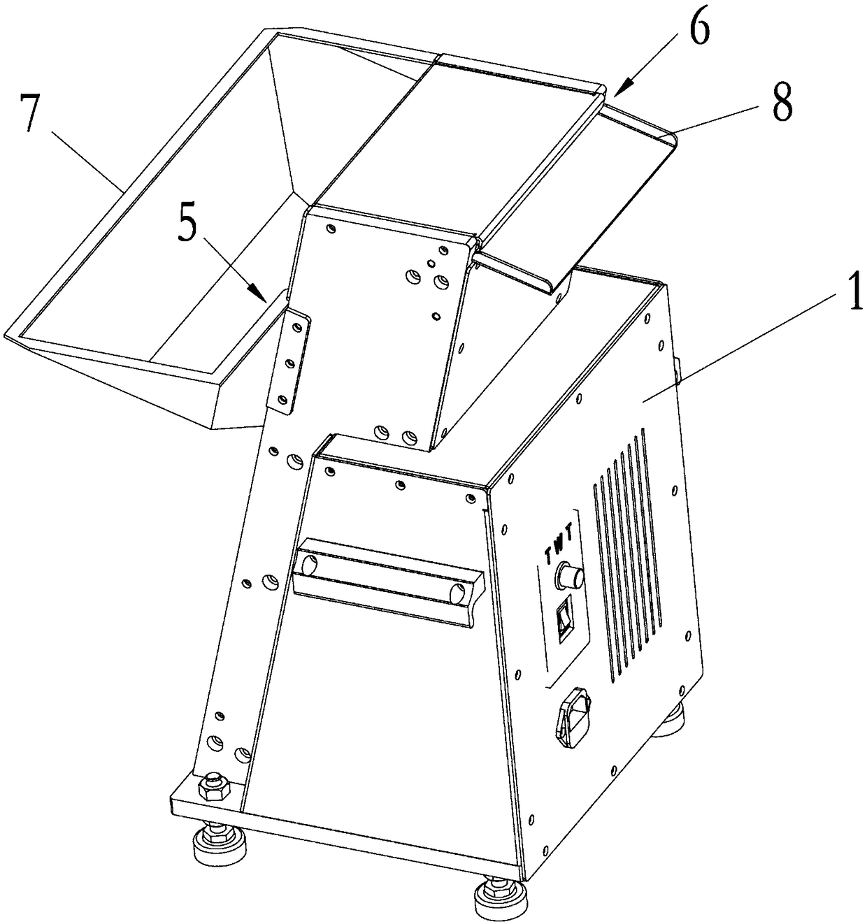
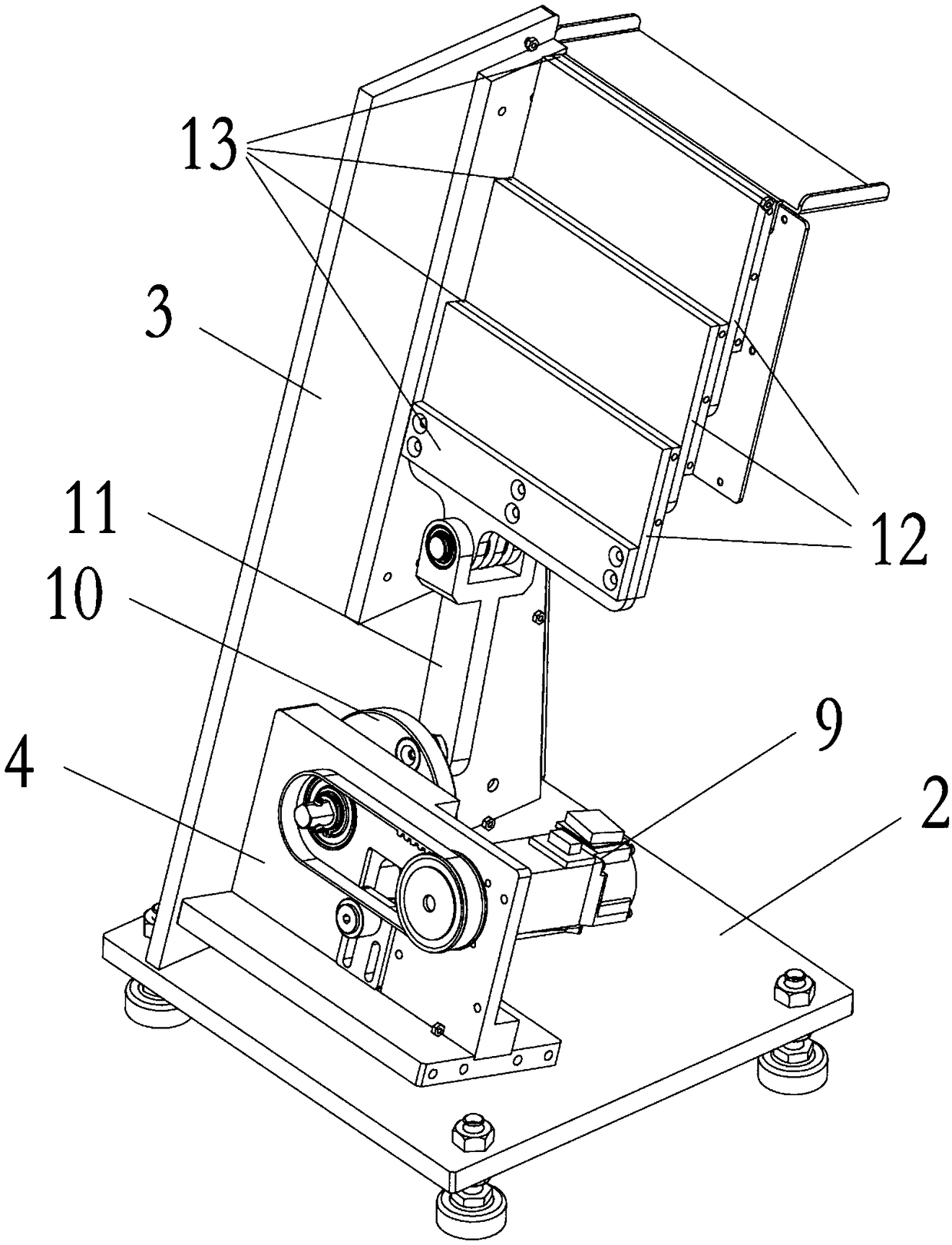
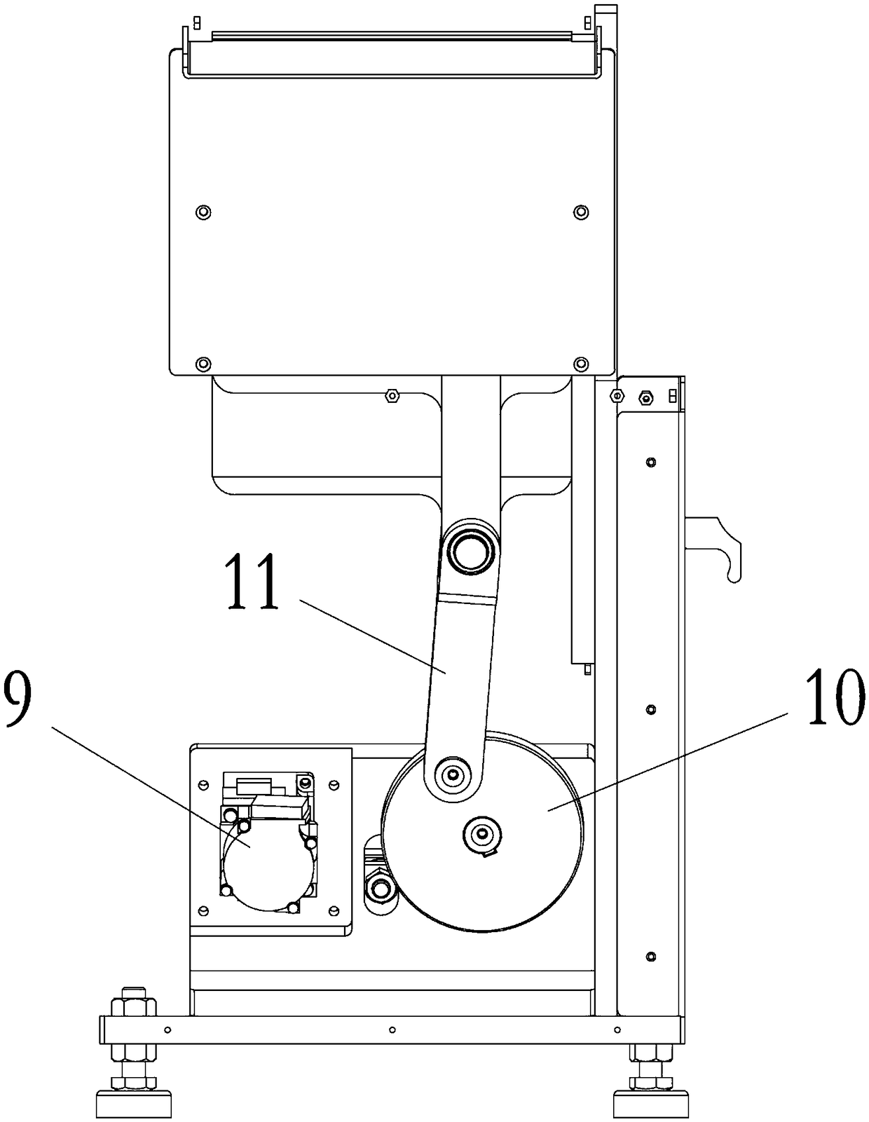
[0023] The invention discloses a fast feeding mechanism for shaft workpieces, such as Figure 1~Figure 5 As shown, it includes: a frame, and an outer cover 1 arranged on the frame. The frame includes a horizontal base 2, which is directly and horizontally placed on the ground or other horizontal surfaces, where the placement can be mobile or fixed. Two vertical boards 3 are fixed on the base 2 , and a base 4 is fixed between the vertical boards 3 . In this preferred embodiment, the base 4 is fixed obliquely, that is, it is set at an angle to the horizontal plane.

[0024] The frame is provided with a feed port 5 and a discharge port 6, the feed port 5 is vertically lower than the discharge port 6, in this preferred embodiment, the feed port 5 is A ...


PUM


Abstract

The invention discloses a rapid feeding mechanism of a shaft workpiece. The mechanism comprises a machine frame, an outer cover is arranged on the machine frame, a feeding port and a discharging portare formed in the machine frame, the feeding port is lower than the discharging port in the vertical direction, and a stepping lifting mechanism is arranged between the feeding port and the discharging port; and the stepping lifting mechanism comprises a reciprocating driving assembly and a reciprocating push plate set, wherein the reciprocating driving assembly drives the reciprocating push plateset to move in a reciprocating mode, and the shaft type workpiece entering from the feeding port is conveyed to the discharging port in a stepping mode. The rapid feeding mechanism has the beneficialeffects that the problem of difficulty in feeding the shaft-type workpiece is effectively solved, ingenious and reliable are achieved, so that the shaft-type workpiece can be quickly and orderly arranged, and the function that the shaft workpiece is conveyed from a low position to a high position is completed.

Description

technical field [0001] The invention relates to the technical field of automation equipment, in particular to a fast feeding mechanism for shaft workpieces. Background technique [0002] At present, automation equipment is generally used in production activities. The advantage of automation equipment is that it can liberate operators well and greatly improve work efficiency. The basic functions of automation equipment generally include feeding area, processing area and unloading area. The feeding area includes the feeding mechanism of the basic workpiece or raw material, whose purpose is to transport the basic workpiece or raw material to the processing area; the processing area is generally the core of the automation equipment, and its purpose is to complete the automatic processing and testing of the basic workpiece or raw material ; The unloading area includes the feeding mechanism of the processed workpieces, the purpose of which is to transport and package qualified wo...

Claims


Application Information

Patent Timeline
Patent Type & Authority Applications(China)
IPC IPC(8): B65G25/08
CPCB65G25/08
Inventor 谭敏王彬孟玉波
Owner JIANGSU XINTIMU INTELLIGENT EQUIP CO LTD
Learn More