
Gas ejection device

An ejection device and gas technology, applied in the direction of the casting line, etc., can solve the problems of death, drowning in the water, and the lifebuoy cannot reach the position of falling into the water, etc., and achieves the effect of convenient operation and simple structure.

Inactive Publication Date: 2019-01-01
义乌市德恒信息科技有限公司
View PDF0 Cites 2 Cited by
  • Summary
  • Abstract
  • Description
  • Claims
  • Application Information

AI Technical Summary

Problems solved by technology

[0002] In daily life, we can often see people falling into the water but can’t swim on the road. Most of the drowning people died when they waited for rescue. When the position is far away, the life buoy cannot reach the position of falling into the water, and sometimes even people who can swim will be accidentally taken into the water and drowned when saving people. In order to save more lives and reduce the occurrence of tragedies, it is necessary to An air-powered life-saving ejection device that can launch life-saving bags and has a long range is set up on the edge of the river

Method used


Image

  • Gas ejection device
  • Gas ejection device
  • Gas ejection device

Examples


Embodiment Construction

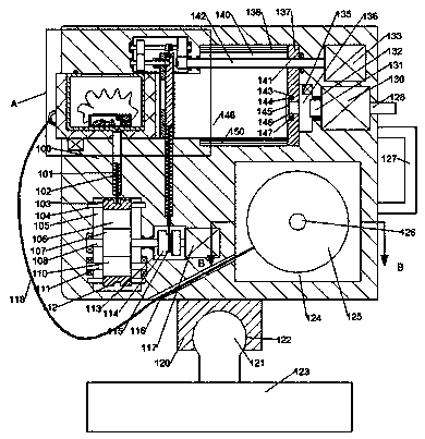
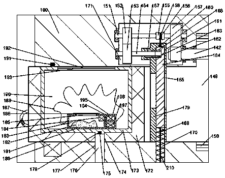
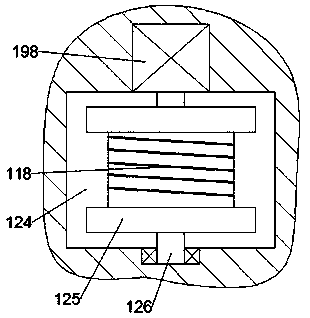
[0014] Combine below Figure 1-3 The present invention will be described in detail.

[0015] refer to Figure 1-3, the gas ejection device according to the embodiment of the present invention includes a device box 100, a first gas compression chamber 148 with an opening to the left is provided in the left end surface of the device box 100, and the first gas compression chamber 148 is right The side communicates with a second gas compression chamber 136, and the first gas compression chamber 148 communicates with a first transmission chamber 140 upwards. The top wall of the first transmission chamber 140 is provided with an upper limit chute 138. The bottom wall of the first gas compression chamber 148 is communicated with a bottom wall limit chute 150, and the right side of the second gas compression chamber 136 is fixed with an air compression pump 130, and the air outlet on the left side of the air compression pump 130 is sealed and installed The air outlet pipe 131, the a...


PUM


Abstract

The invention discloses a gas ejection device, comprising a device box, wherein the end surface of the left side of the device box is provided with a first gas compression chamber opening to the left;the right side of the first gas compression chamber is communicated with a second gas compression chamber; the first gas compression chamber is communicated upward with a first transmission chamber;an upper limiting chute is formed in the top wall of the first transmission chamber; the bottom wall of the first gas compression chamber is communicated with a bottom wall limiting chute; an air compression pump is fixedly mounted on the right side of the second gas compression chamber; an air outlet pipeline is sealed at an air outlet of the left side of the air compression pump; the air outletpipeline extends leftward through the inner wall of the right side of the second gas compression chamber and enters the second gas compression chamber; an air inlet pipeline is sealed at an air inletof the right side of the air compression pump; the air inlet pipeline extends rightward through the end surface of the right side of the device box.

Description

technical field [0001] The invention relates to the field of river rescue, in particular to a gas ejection device. Background technique [0002] In daily life, we can often see people falling into the water but can’t swim on the road. Most of the drowning people died when waiting for rescue. When the position is far away, the life buoy cannot reach the position of falling into the water, and sometimes even people who can swim will be accidentally taken into the water and drowned when saving people. In order to save more lives and reduce the occurrence of tragedies, it is necessary to The utility model relates to a life-saving ejection device which is set on the edge of a river, uses air as power, and can launch a life-saving bag and has a relatively long shooting range. Contents of the invention [0003] The object of the present invention is to provide a gas ejection device for overcoming the above-mentioned defects in the prior art. [0004] The gas ejection device acc...

Claims


Application Information

Patent Timeline
IPC IPC(8): B63C9/26
CPCB63C9/26
Inventor 寿金校
Owner 义乌市德恒信息科技有限公司
Learn More