
Mould assembly for producing prefabricated component and stirrup positioning method utilizing mould assembly

A technology of prefabricated components and stirrups, which is applied in the field of positioning of stirrups and the production of mold components for prefabricated components, and can solve the problems of increasing the difficulty of manufacturing prefabricated components, the position of stirrups is easy to shift, and the positioning of stirrups is difficult.

Pending Publication Date: 2019-01-01
CHANGSHA BROAD HOMES IND FUYANG CO LTD
View PDF0 Cites 0 Cited by
  • Summary
  • Abstract
  • Description
  • Claims
  • Application Information

AI Technical Summary

Problems solved by technology

[0004] Based on this, it is necessary to solve the problem that the stirrups are difficult to locate in the production process of the existing prefabricated components, which leads to the easy deviation of the position of the stirrups and increases the difficulty of manufacturing the prefabricated components. Mold assembly for producing prefabricated components and stirrup positioning method using the mold assembly

Method used


Image

  • Mould assembly for producing prefabricated component and stirrup positioning method utilizing mould assembly
  • Mould assembly for producing prefabricated component and stirrup positioning method utilizing mould assembly
  • Mould assembly for producing prefabricated component and stirrup positioning method utilizing mould assembly

Examples


Embodiment Construction

[0028] In order to facilitate the understanding of the present invention, the present invention will be described more fully below with reference to the associated drawings. Preferred embodiments of the invention are shown in the accompanying drawings. However, the present invention can be embodied in many different forms and is not limited to the embodiments described herein. On the contrary, these embodiments are provided to make the understanding of the disclosure of the present invention more thorough and comprehensive.

[0029] Unless otherwise defined, all technical and scientific terms used herein have the same meaning as commonly understood by one of ordinary skill in the technical field of the invention. The terms used herein in the description of the present invention are for the purpose of describing specific embodiments only, and are not intended to limit the present invention. As used herein, the term "and / or" includes any and all combinations of one or more of ...


PUM


Abstract

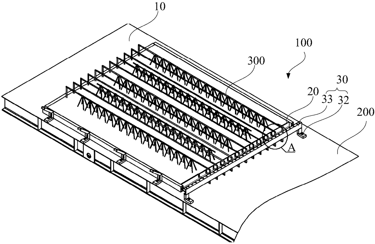
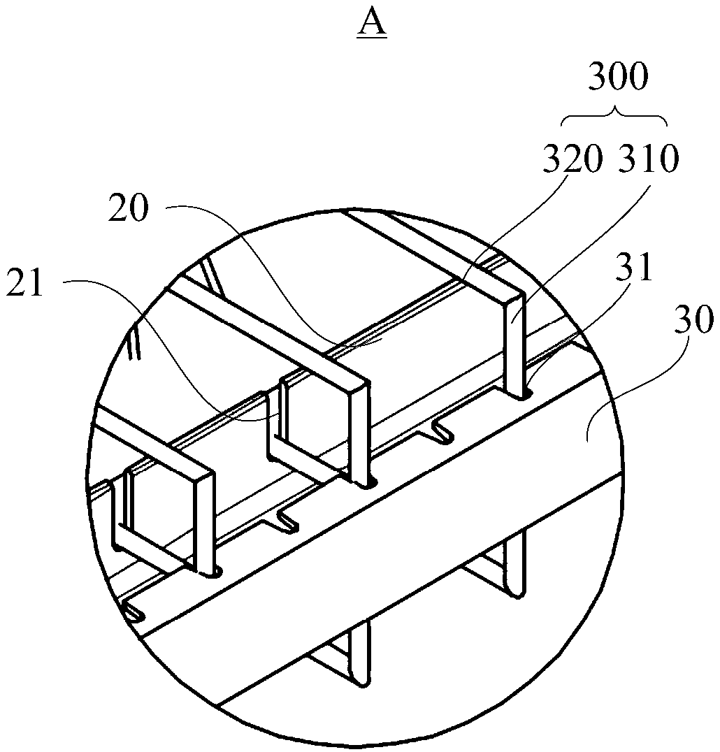
The invention relates to a mould assembly for producing a prefabricated component and a stirrup positioning method utilizing the mould assembly. The mould assembly for producing the prefabricated component comprises a first blocking side moulding board, a second blocking side moulding board and a stirrup positioning mould, wherein the first blocking side moulding board and the second blocking sidemoulding board are oppositely arranged; the stirrup positioning mould is positioned at one side, back to the first blocking side moulding board, of the second blocking side moulding board, and is spaced with the second blocking side moulding board; the first blocking side moulding board abuts against the bending part at one end of a stirrup; the second blocking side moulding board is equipped with a stirrup penetrating slot for allowing the stirrup to penetrate through in a longitudinal length direction; one side, towards the second blocking side moulding board, of the stirrup positioning mould is equipped with a positioning part; and the positioning part is matched with the bending part of the stirrup, so that the bending part is positioned on the positioning part, and therefore, the stirrup is positioned between the first blocking side moulding board and the stirrup positioning mould. According to the mould assembly for producing the prefabricated component and the stirrup positioning method utilizing the mould assembly provided by the invention, the two ends of the stirrup are positioned reliably, so that the position of the stirrup is guaranteed to not shift.

Description

technical field [0001] The invention relates to the technical field of building prefabricated parts production, in particular to a mold assembly for producing prefabricated components and a stirrup positioning method using the mold assembly. Background technique [0002] Concrete prefabricated components are made of concrete as the basic material, and are prefabricated in the factory through the processes of laying molds, laying reinforcement, pouring concrete, and curing molding, including prefabricated building components such as walls, beams, slabs, and columns. In field construction, since prefabricated components need to be connected with other components, in order to ensure the connection strength, protruding tendon structures are often reserved at the ends of prefabricated components. When the ends of the two ribs of the prefabricated component are connected by steel bars to form a sealed structure, the ribs at this time are called stirrups. [0003] At present, pref...

Claims


Application Information

Patent Timeline
Patent Type & Authority Applications(China)
IPC IPC(8): B28B7/22
CPCB28B7/22
Inventor 张剑王雅明朱彦哲徐雷
Owner CHANGSHA BROAD HOMES IND FUYANG CO LTD
Learn More